Table of Contents
Advertisement
Quick Links
Advertisement
Table of Contents

Related Manuals for MCE R.45.TC.PRO

Summary of Contents for MCE R.45.TC.PRO
- Page 1 Bandwidth FINE WIDE Brightness Power DB.UNI.PRO OPERATOR’S MANUAL...
- Page 2 This manual is an important part of your purchase. Please read it thoroughly before using your R.45 TC or R.45.TC.PRO laser receiver. We recommend that you record details of your purchase here so that the information is readily available if you ever need to contact your supplier.
- Page 3 WARRANTY STATEMENT OF LIMITED WARRANTY MOBA Australia warrants all equipment of its manufacture to be free of defects in material and workmanship for a period of twelve months. his warranty period is twelve months from the date of invoice. tems covered by this warranty are: sensors, transmitters, electronic levels, receivers, masts, control boxes, displays and accessories.
- Page 4 SAFETY INFORMATION Please become familiar with the important safety information in this section. Improper use or installation of the MCE Laserguide may result in personal injury or damage to the receiver unit. 1. Read and become familiar with the manufacturer’s operating manual for your machine, including safety information, before installing or using your Laserguide receiver.
-
Page 5: Table Of Contents
CONTENTS 1. Features of the Laserguide ................6 2. Using the Laserguide ..................7 2.1 Powering Up ....................7 2.2 Mounting And Setting Up ................7 2.2.1 With tilt compensation ................7 2.2.2 Without tilt compensation ..............8 2.3 Switching Compensation On/Off and Setup Length Selection ....10 2.4 Zeroing .....................10 2.5 Compensation Range ................11 2.6 Accuracy (Centre Band) ................11... -
Page 6: Features Of The Laserguide
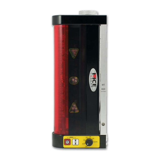
FEATURES OF THE LASER GUIDE Adjustable accuracy and tilt compensation. 1. Magnetic bracket 7. Bottom LED cluster (Orange) 2. Receiving area 8. Accuracy switch 3. Top LED cluster (Red) 9. Reference dial 4. Center LED cluster (Green) 10. On/Off switch 5. -
Page 7: Using The Laserguide
L = HI + C The dipper arm should be vertical, the bucket levelled, the R.45.TC /R.45.TC.PRO body should be parallel with the dipper arm and in line with the top and bottom pivot pins of the dipper arm. The battery compartment should be pointing down. -
Page 8: Without Tilt Compensation
2.25m or 2.5m. For most applications, a Setup Length as close as possible to one of these values is adequate. The measured Setup Length should be stored in the RR.45.TC/R.45.TC.PRO by following the steps in sections 2.3 and 2.4. 2.2.2 WITHOUT TILT COMPENSATION If intending not to use the compensation feature, distance L should be measured from the ground to the centre green LED cluster instead of the ‘MT REF’... - Page 9 In trench setup FIGURE1 Out trench setup FIGURE1...
-
Page 10: Switching Compensation On/Off And Setup Length Selection
LED cluster and sounding the buzzer, or it indicates a failed attempt by briefly flashing the red and amber LED clusters concurrently. A failed attempt can be caused if the R.45.TC/R.45.TC.PRO is angled too far from the vertical or if the compensation feature is switched off. Check both and try again. -
Page 11: Compensation Range
2.6 ACCURACY (CENTER BAND) The R.45.TC/R.45.TC.PRO has three different accuracy or centre band settings - Fine, Normal and Wide. Each setting is indicated by briefly flashing a different LED cluster pattern as shown in the table below. The current selection is shown on power up, at the end of the power up sequence, or when changing the centre band. -
Page 12: Buzzer
2.8 LED BRIGHTNESS To increase or decrease the brightness of the LEDs, press and hold the accuracy switch on the R.45.TC/R.45.TC.PRO in the same manner as when changing the accuracy setting. When the LED cluster pattern of the new accuracy setting lights up, do not release the accuracy switch and press and release the on/off switch. -
Page 13: Remote Control
REMOTE CONTROL The remote control gives full control of the sensor. A summary of button operation is given below. Press to switch buzzer on/off. Press to change the current accuracy (Centre Band) setting. Press to change the brightness level of the LEDs to suit the surroundings. -
Page 14: Bluetooth Communication Setup
LED will flash quickly once Bluetooth connection is established it will flash slowly. Step 8) If setup fails, switch off the R.45.TC.PRO. Upon switching on press and hold the switch button for 20 secs until you here 2 long beeps. Repeat... - Page 15 Step 7) If the setup fails at any stage a X will flash on the DB.UNI.PRO, repeat the above steps. Step 8) If setup fails, switch off the R.45.TC.PRO. Upon switching on press and hold the switch button for 20 secs until you here 2 long beeps. Repeat steps 2 to 7.
-
Page 16: Can Communication Setup
Xsite excavator systems via CAN cable 5.1 COMMUNICATING WITH THE DB.UNI.PRO Step 1) Ensure that the CAN cable is used to connect the R.45.TC.PRO to the DB.UNI.PRO. Step 2) Ensure that the DB.UNI.PRO is connected to 12VDC via the supplied power cord. - Page 17 5.2 COMMUNICATING WITH THE MOBA XSITE 2D EXCAVATOR RANGE Step 1) Ensure that the CAN cable is used to connect the R.45.TC.PRO to the MOBA Xsite 2D excavator system. Step 2) Follow the normal calibration procedure in the MOBA XSITE manual Step 3) Please contact MCE Lasers for mounting instructions.
-
Page 18: Technical Specifications
TECHNICAL SPECIFICATIONS R.45.TC R.45.TC.PRO Receiver Area Length 190mm 190mm Receiving Range (Radius)* 500 m 500 m +/- 4 mm +/- 4 mm Centre Band Resolution Up to 31 degrees Up to 31 degrees Compensation Range Battery Type 1 D size Alkaline 4 C size Alkaline 45 hours (buzzer off)*... - Page 20 A U S T R A L I A P T Y L T D MOBA MOBILE AUTOMATION AUSTRALIA PTY LTD ABN - 866 279 713 68 90 Willandra Drive, Epping, Victoria, Australia 3076 Ph: +61 3 9357 0055 Email: aumoba@moba.de www.moba-automation.com.au...
Need help?
Do you have a question about the R.45.TC.PRO and is the answer not in the manual?
Questions and answers