Table of Contents
Advertisement
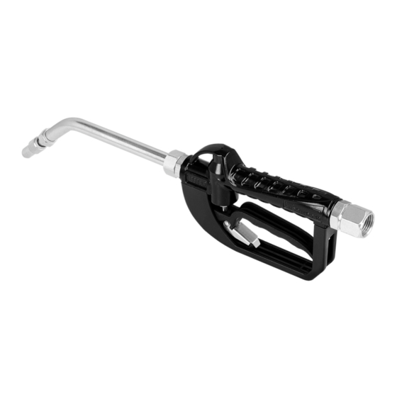
35L Oil Control Valve
Instruction Manual
WARNING:
Read carefully and understand all INSTRUCTIONS before operating. Failure to follow the safety
rules and other basic safety precautions may result in serious personal injury.
Save these instructions in a safe place and on hand so that they can be read when required.
Keep these instructions to assist in future servicing.
REV 08/11/17
Advertisement
Table of Contents

Related Manuals for Lubeworks 18063521

Summary of Contents for Lubeworks 18063521
- Page 1 35L Oil Control Valve Instruction Manual WARNING: Read carefully and understand all INSTRUCTIONS before operating. Failure to follow the safety rules and other basic safety precautions may result in serious personal injury. Save these instructions in a safe place and on hand so that they can be read when required. Keep these instructions to assist in future servicing.
-
Page 2: General Safety Regulations
GENERAL SAFETY REGULATIONS WARNING: The warnings, cautions, and instructions discussed in this instruction manual cannot cover all possible conditions or situations that could occur. It must be understood by the operator that common sense and caution are factors that cannot be built into this product, but must be supplied by the operator. -
Page 3: Technical Details
TECHNICAL DETAILS Item No. 18063521 18063526 18063531 18063536 18163521 18163526 18163531 18163536 Inlet connection 1/2” Fluid Range 1~35L/M(0.3~9.25gpm) 0.5-100bar / 7-145psi 5-100Bar / 70-145psi 0.5-50bar / 7-725psi 5-50Bar / 70-725psi Pressure Range Min. -10°C Max. 60°C Min. -10°C Max. 60°C Temperature ±0.5%... -
Page 4: Change The Battery
2. CHANGE THE BATTERY • Battery type: Lithium CR2, 3V/1400mAh • Last for 8 years of operation, corresponds to approx. 500,000 litres (132,000 US GAL) • Change the battery like below when the battery signal is flashing on the display •... - Page 5 • Show current correction factor and general total (See Fig. 5) Press MOVE and RESET together and hold for less than 3 seconds. Value “1.4000” is the correction factor which can be reset; “1234567” is the general total which cannot be reset.
- Page 6 PROCEDURE FOR ENTER THE CORRECTION FACTOR DIRECTLY Carefully follow the procedure indicated below. FORMULA Proper correction factor = current correction factor×(actual value/ display value) Example: Actual value 20.75 Display value 18.96 Current correction factor 1.000 Proper correction factor 1.000×(20.75/18.96)=1.000×1.094=1.094 Wait for the meter to go standby. Reset the resettable total.
- Page 7 MODIFY THE CORRECTION FACTOR IN FIELD PLEASE CAREFULLY FOLLOW THE PROCEDURE INDICATED BELOW. Wait for the meter to go standby. Reset the resettable total. Start dispensing into a measuring glass. Stop dispensing when over 5 Litres of volume is reached, read out the actual value.
-
Page 8: Usage Instruction
USAGE INSTRUCTION (1) Start: Turn on the trigger to make the oil transmission. (2) Keep the status: Push the lock ahead, then the transmission can be kept when the trigger is released. (3) Finish: a. If the lock is not used, release your hand, the trigger will turn off and finish the transmission. -
Page 9: Troubleshooting Guide
TROUBLE SHOOTING GUIDE Relieve the pressure before you check or repair the dispensing valve. Be sure all other valves and controls and the pump are operating properly. To reduce the risk of serious injury whenever you are instructed to relieve pressure, always follow the pressure relief procedure on page 3. - Page 10 EXPLODED AND PARTS LIST #15210601 Part No. Description Q’ty Part No. Description Q’ty Rubber Protector 2-10 Screw Meter Cover 2-11 Label Main Circuit Board 2-12 Screw Fix Board 2-13 Battery Seat 2-14 Battery Cover Magnetic Rod 2-15 Screw Oval Gear 2-16 Screw O-ring...
- Page 11 EXPLODED AND PARTS LIST VALVE BODY EXPLORED DRAWING 4-10 4-11 4-12 4-13 4-14 4-15 4-16 4-17 4-18 Part No. Description Q’ty Part No. Description Q’ty Handle Body 4-10 Washer Trigger 4-11 Seal Grip 4-12 Slip Pole Screw 4-13 O Ring Trigger Lock 4-14 O Ring...
- Page 12 Intradin (Shanghai) Machinery Co., Ltd. iti-fluid@intradinchina.com www.intradin.com Size: 145x210mm 157克铜版纸 REV 08/11/17 2.09.05.30.634...
Need help?
Do you have a question about the 18063521 and is the answer not in the manual?
Questions and answers