Table of Contents
Advertisement
Available languages
Available languages
MANUALE INSTALLAZIONE E REGOLAZIONE
INSTALLATION AND ADJUSTMENT MANUAL
MANUEL INSTALLATION ET REGLAGE
GUIA INSTALLACION Y REGULACION
LAMBDA CONTROL SYSTEM A1 V05
LANDI RENZO S. p. A. - Via F.lli Cervi, 75/2 - 42100 Reggio Emilia - Italy
LPG & CNG CONVERSION SYSTEMS FOR VEHICLES
Tel. +39 / 05 22 38 26 78 - Fax +39 / 05 22 38 29 06
E-mail: Info@landi.it - http://www.landi.it
pag.
6
page
13
page
20
pag.
27
Advertisement
Table of Contents

Related Manuals for Landi Renzo A1 V05


Summary of Contents for Landi Renzo A1 V05
- Page 1 LPG & CNG CONVERSION SYSTEMS FOR VEHICLES LANDI RENZO S. p. A. - Via F.lli Cervi, 75/2 - 42100 Reggio Emilia - Italy Tel. +39 / 05 22 38 26 78 - Fax +39 / 05 22 38 29 06...
- Page 2 Schéma Technique Gpl Schema Tecnico Gpl Esquema Técnico Glp Lpg Technical Drawing Fig. 1 LANDI RENZO S.p.A. LAMBDA CONTROL SYSTEM A1 V05 2 / 33...
- Page 3 Schéma Technique Gnc Schema Tecnico Metano Esquema Técnico Gnc Cng Technical Drawing Fig. 2 LANDI RENZO S.p.A. LAMBDA CONTROL SYSTEM A1 V05 3 / 33...
- Page 4 LCS AG DGM 48522 GPL DEL 24-1-94 LCS AM DGM 48523 GM DEL 24-1-94 LCS AM DGM 48523 GM DEL 24-1-94 Fig. 3 Fig. 4 Fig. 5 Fig. 6 LANDI RENZO S.p.A. LAMBDA CONTROL SYSTEM A1 V05 4 / 33...
-
Page 5: Technical Drawings
Technical Drawings +12 V + 5 V Segnale TPS Segnale TPS TPS signal TPS signal Signal TPS Signal TPS Señal TPS Señal TPS Fig. 7 Fig. 8 Fig. 9 LANDI RENZO S.p.A. LAMBDA CONTROL SYSTEM A1 V05 5 / 33... -
Page 6: Specifiche Tecniche
- Tensione di lavoro: 12V - Corrente assorbita: 150mA - Potenza nominale: 2W - Temperatura di funzionamento: -20°C / +120°C - Grado di protezione da polvere ed acqua: IP65 LANDI RENZO S.p.A. MANUALE INSTALLAZIONE E REGOLAZIONE LAMBDA CONTROL SYSTEM A1 V05 6 / 33... - Page 7 La sonda lambda posta nel collettore di scarico rivolto verso il basso per evitare che eventuali indica il rapporto di miscela ed in ogni istante invia infiltrazioni di acqua penetrino all’interno del un valore di tensione al Computer LCS A1 V05 il Computer. quale verifica miscela é...
- Page 8 • lampeggio lento: indica il malfunzionamento originale dell’impianto elettrico dell’auto (es. del sistema LCS A1 V05 durante l’utilizzo a gas massa del computer benzina o massa di altri (vedi par. 5.3). dispositivi come ABS, idroguida, ecc.). (C) led giallo •...
-
Page 9: Collegamenti Elettrici
LCS A1 V05. isolato). - sensore tipo A.E.B. : collegare i fili verde e bianco del cablaggio LCS A1 V05 ai rispettivi fili verde e bianco del sensore livello gas. LANDI RENZO S.p.A. MANUALE INSTALLAZIONE E REGOLAZIONE LAMBDA CONTROL SYSTEM A1 V05... - Page 10 - sensore tipo 0-90 Ω: collegare entrambi i fili 7. FUNZIONAMENTO DI LCS A1 V05 Le funzioni programmabili di LCS A1 V05 possono verde e bianco del cablaggio LCS A1 V05 al filo essere modificate solamente tramite l’ apposito del sensore livello gas.
- Page 11 SCONNESSA (0,00 SEC.), NUMERO ONDE DOPO Ì MASSA. In questi veicoli si collega il filo giallo- SCONNESSIONE (0) blu del cablaggio LCS A1 V05 al filo n. 2 (anziché - SCOSTAMENTO ATTUATORE-MAX IN ACCELERA- al filo n. 4) del connettore TPS posto a fianco del ZIONE: corpo farfallato.
- Page 12 Computer LCS da dare al sistema il tempo di scaricare i circuiti A1 V05 e verificare che assuma i valori standard interni. Dopodiché si potrà procedere con una evidenziati in neretto nel paragrafo 7.2;...
-
Page 13: Specification
6. - Power absorption: 150mA - Nominal power: 2W - Operating temperature: -20°C / +120°C - Water and dust protection level: IP65 LANDI RENZO S.p.A. INSTALLATION AND ADJUSTMENT MANUAL LAMBDA CONTROL SYSTEM A1 V05 13 / 33... - Page 14 Parts installation 2. LCS A1 V05 FUNCTIONS 3. INSTALLATION OF COMPUTER LCS A1 V05 LCS A1 V05 is used with following Lpg or Cng (Fig. 3) LANDI RENZO pressure regulator: SE 81, SE 81 The Computer must be attached to the car chassis SIC, TN1, TN1/B, TN1 SIC, TN1/B SIC.
- Page 15 In some model of vehicles it could be necessary to 5.2 EMERGENCY STARTING ON GAS WITH connect only the violet wire of the LCS A1 V05 SWITCH / GAUGE LCS A1 V05 Computer, while the grey one will be properl In case of malfunctioning during the petrol starting insulated.
-
Page 16: Electrical Connections
- LANDI RENZO type Lpg/Cng sensor: connect performed with reference to ground) and connect the white wire of LCS A1 V05 to the white wire of the same to the blue-yellow wire of the LCS A1 the gas level sensor; the green wire remains V05. - Page 17 • TPS LEARNING RANGE: indicate if you are in overlapping time, connect one end of the yello an idling condition, cruise condition or maximum wires of LCS A1 V05 to ground and the other to open throttle condition the special connector on the electronic emulator.
- Page 18 0,000 - 1,000 SEC. (0,400 SEC.) enabled) - TPS (THROTTLE POSITION SENSOR): - LCS A1 V05 MEMORY RESETTING: OK TO CONFIRM LINEAR 0-5V, LINEAR 5 - 0V, SWITCH 0 - 12V, allows to re-set the standard values (in bold type) of LCS...
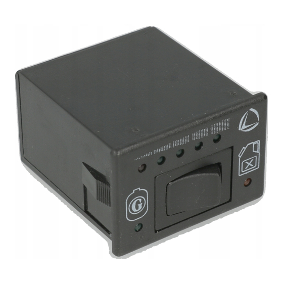
- Page 19 7.4 MALFUCNTIONING DIAGNOSIS The Switch / Gauge LCS A1 V05 is in the position f) Enter in the ‘DISPLAY’ page of the Programming to point out to the installer or the driver some error Tester V05 (or personal computer).
- Page 20 - Tension de travail: 12V - Courant absorbé: 150mA - Puissance nominale: 2W - Température de travail: -20°C / +120°C - Degré de protection contre poudre et eau: IP65 LANDI RENZO S.p.A. MANUEL INSTALLATION ET REGLAGE LAMBDA CONTROL SYSTEM A1 V05 20 / 33...
- Page 21 à chaque instant envoie une valeur de tension à INSTALLATION ACTUATEUR ELECTRO- l'ordinateur LCS A1 V05 qui vérifie si le mélange MECANIQUE LINEARE (Fig. 4) est correct, en le comparant avec la valeur en L’Actuateur Electromécanique Linéaire doit être mémoire;...
- Page 22 5.2 DEMARRAGE EN EMERGENCE A GAZ LCS A1 V05 avec les deux fils obtenu depuis avoir AVEC LE COMMUTATEUR / INDICATEUR LCS coupé le fil du signal qui sort de la sonde lambda.
- Page 23 - senseur Gpl/Cng type LANDI RENZO: brancher TPS proportionnel comme le sous indiqué. Le le fil blanc du câblage LCS A1 V05 au fil blanc du signal qui sort de ce type de TPS présente senseur niveau gaz et ne brancher pas le fil vert seulement 2 conditions: 0 Volt avec papillon (qui doit être isolé).
- Page 24 6.7 FILS JAUNES (Fig. 9) INTERRUPTION INJECTEURS Par le Testeur Programmateur V05 (ou personal Les fils jaunes du câblage LCS A1 V05 sont computer avec Kit Interface V05 installé) on peut branches a un relay normalement fermé. Pendant afficher les suivantes paramètres: le fonctionnement a gaz, (Fig.
- Page 25 400 - 9.000 RP (2.000 RPM) CONFIRMER permette de retablir les parametres - TEMPS SOVRAPPOSITION CARBURANTS: standard (en caracter gras) du Computer LCS A1 V05 0,000 - 1,000 SEC. (0,400 SEC.) OBSERVATIONS CONCERNANT LA - TPS (SENSEUR POSITION PAPILLON D’ACCELERA-...
- Page 26 Computer LCS A1 V05 a les 7.4 DIAGNOSIS MALFONCTIONNEMENT caractéristiques véhicules répéter la Le Commutateur / Indicateur LCS A1 V05 est en vérification. mesure de mettre en évidence a l’installateur et a e) Démarrer le moteur avec le Commutateur / l’utilisateur des contions d’erreur.
-
Page 27: Especificaciones Técnicas
- Tensión de trabajo: 12V - Corriente absorbida: 150mA - Potencia nominal: 2W - Temperatura de funcionamiento: -20°C / +120°C - Grado de protección de polvo y agua: IP65 LANDI RENZO S.p.A. GUIA INSTALLACION Y REGULACION LAMBDA CONTROL SYSTEM A1 V05 27 / 33... - Page 28 La sonda lambda puesta en el colector de Computer. descarga, indica la relación de mezcla y en cada instante envía un valor de tensión al Computer LCS A1 V05 el cual verifica si la mezcla es INSTALACION ACTUADOR ELECTRO- correcta comparando dicho valor con el valor MECANICO LINEAR (Fig.
- Page 29 • destello lento: indica el malfuncionamento del implanto eléctrico del vehículo (ex. masa del sistema LCS A1 V05 durante el utilizo a gas (ver computer gasolina o masa de otros dispositivos par. 5.3). como ABS, etc.).
- Page 30 LCS A1 V05. La tensión en este hilo varia CONEXION 12V CUADRO CONECTADO respecto a la mas de 0 a 5V. Conectar el hilo rojo del cableado LCS A1 V05 a un dispositivo cuadro conectado como por • TPS de tipo "switch" (Fig. 7B) : los hilos...
-
Page 31: Conexiones Eléctricas
- sensor tipo 0-90 Ω: conectar ambos los hilos 7. FUNCIONAMENTO DE LCS A1 V05 Las funciones programables de LCS A1 V05 verde y blanco del cableado LCS A1 V05 al hilo pueden ser modificadas solamente tramite el del sensor nivel gas. - Page 32 DESHABILITADA, 40 - 240 PASOS (80 PASOS si En caso de mensajes de error sobre el display del habilitada) Tester Programador V05 (o del personal computer LANDI RENZO S.p.A. GUIA INSTALLACION Y REGULACION LAMBDA CONTROL SYSTEM A1 V05 32 / 33...
- Page 33 3 minutos para dar al sistema el tiempo de en el parrafro 7.2; adecuar sucesivamente otra descargar los circuitos internos. Después se podrá vez los parámetro del Computer LCS A1 V05 a las proceder con una nueva programación. características del vehículo y repetir la verifica.
Need help?
Do you have a question about the A1 V05 and is the answer not in the manual?
Questions and answers