Table of Contents
Advertisement
Quick Links
Advertisement
Table of Contents

Related Manuals for Jäger Z80-K440.54 S4W2IP


Summary of Contents for Jäger Z80-K440.54 S4W2IP
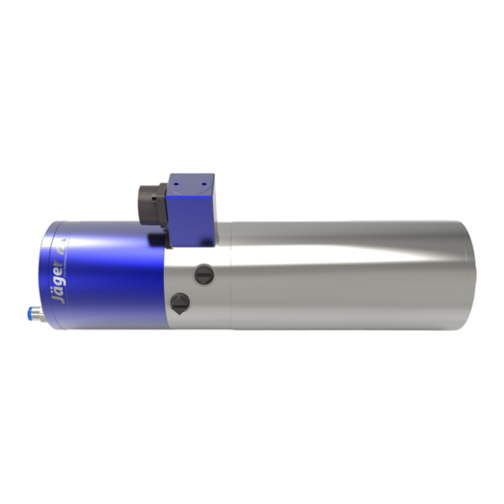
- Page 1 Manual Z80-K440.54 S4W2IP High Frequency Spindle Pneumatic taper change...
- Page 2 Identification of HF spindle Spindle type Item no. Serial no. Spindle type Item no..Serial no. Pmax S6-60% S1-100% Rated rotation speed Performance data As we always ensure that our HF spindles are at the cutting edge of techno- logical development, we reserve the right to make technical modifications and variations from the exact design described in the manual.
-
Page 3: Table Of Contents
Contents: Translation of the original manual Diameter of media supply line........ 21 Preliminary information 4 Cooling water............... 21 Purpose of the manual............ 4 8.3.1 Quality of cooling water........ 21 Explanation of symbols used........... 4 8.3.2 Setting the cooling.......... 21 Transport and packaging 5 Compressed air.............. -
Page 4: Preliminary Information
Preliminary information Preliminary information The high frequency spindle (HF spindle) is a high quality precision tool for high speed machining. Purpose of the manual The manual is an important component of the HF spindle. Ü Store the manual carefully. Ü Make the manual available to all persons who work with the HF spindle. -
Page 5: Transport And Packaging
Transport and packaging Transport and packaging Avoid strong vibrations or impacts during transportation, as these could dam- age the ball bearings of the HF spindle. Ü Any damage reduces the accuracy of the HF spindle. Ü Any damage restricts the functionality of the HF spindle. Ü... -
Page 6: Documentation Supplied
Designated use 2.1.3 Documentation supplied The documents listed below are supplied with the HF spindle: Manual The declaration of incorporation is part of the manual. Inspection protocol Ü Check that the documentation supplied is complete when the spindle is delivered. If necessary, request a new copy. Packaging of HF spindle All transport packaging materials can be recycled in appropriate disposal facil- ities. -
Page 7: Safety Instructions
Safety instructions Safety instructions The high frequency spindle is a state of the art product and is safe to operate. However, the HF spindle may pose a risk in the following cases: If it is installed by untrained personnel. If it is used incorrectly. If it is not used in accordance with its intended use. - Page 8 Safety instructions DANGER: Due to flying parts. Tools that are not clamped correctly will be flung away by the centrifugal forces that occur during machining. Use the full clamping depth of the collet. Clamp the tool securely. DANGER: Due to flying parts. If the wrong rotational direction is used, the clamping system releases and the tool is flung away.
-
Page 9: Shutdown Of Hf Spindle
Safety instructions The tool cutting diameter (X) must not be greater than the maximum clamping range (Y). Ü Always clamp the tool so that it is as short as possible. Ü Keep the dimension (Z) small. Ä (Y) See section: Technical Specifications 12]. -
Page 10: Technical Description
Technical description Technical description Connections of HF spindle Electrical connection Cooling water G 1/8" Sealing air G 1/8" Taper cleaning G 1/8" Pneumatic system for tool change G 1/8" Cylinder vent G 1/8" Electrical connection The HF spindle may only be operated with a frequency converter (FC). Ü... -
Page 11: Cooling
Technical description Cooling Liquid cooling keeps the HF spindle at a constant temperature during opera- tion. Note: Extension of the service life through heat dissipation. Heat is produced during operation of the HF spindle. The temperature of the HF spindle should not exceed + 45° C as this shortens the service life of the bearing. - Page 12 Technical Specifications Technical Specifications Bearings Hybrid ball bearing (pcs) Lifetime lubricated maintenance free Power values Pmax / 5 s S6-60% S1-100% Liquid cooled Rated power [kW] Voltage Current Motor data 3-phase asynchronous drive Motor technology (no brushes or sensors) Frequency 1.333 Hz Motor poles (pairs) Rated rotation speed...
-
Page 13: Dimensions
Technical Specifications Weight ~ 6 kg Inner taper run out < 1 µ Axial run-out < 1 µ Dimensions (*) = Clamping range Item no. 10404146, Revision 00 13 ( 40 ) -
Page 14: Technical Data Sheet (Kl 3033, Ac Motor)
Technical Specifications Technical data sheet (KL 3033, AC motor) The power values (S1, S6, S2) are Motor type 3/7-4 valid for sinusoidal currents and voltages. Rated power 2,6 kW The power values of the HF spin- Rated rotation speed 40.000 rpm dle are dependent on the fre- quency converter used and may Cooling... -
Page 15: Performance Diagram
Technical Specifications Measured values: S2-Pmax./5 s Rated rotation speed 5,000 10,000 15,000 20,000 25,000 30,000 35,000 40,000 Speed 3,804 8,718 10,330 18,740 23,160 26,040 33,460 38,600 Frequency 1,000 1,167 1,333 Rated power 0.233 0.753 1.16 2.13 3.13 3.91 5.02 Torque 0.59 0.82 1.06... -
Page 16: Wiring Diagram
Technical Specifications Wiring diagram Note: Do not change the ex-works configuration. Any change may cause overvoltage on the electrical components (e.g. PTC, differential magneto resistor). Gerätestecker FS9 (S5) spindle plug FS9 (S5) 0,75mm² GNYE *RD/ **BN/ ***RD Stator *BU/ **VT/ ***GN *WH/ **WH/ ***WH 0,14 mm²... -
Page 17: Motor Protection Pt1000
Technical Specifications Motor protection Pt1000 Platinum temperature sensor Design according to: DIN EN 60751 Accuracy class B 2-wire connection Technical Specifications Temperature/resistance correlation (series of basic values) /°C (*) Resistance at temperature t /°C [Ω] 1000 1004 1008 1012 1016 1020 1023 1027... -
Page 18: Tool Change Monitoring
Technical Specifications Tool change monitoring Tool taper monitoring indicates the readiness status of the HF spindle to the operator and forwards the corresponding signal to the machine controller. Tool taper monitoring using inductive proximity switch. Signals Tool clamped HF spindle Ready to operate Operating voltage range: BN (1) -
Page 19: Air-Borne Noise Emissions
Operating location Air-borne noise emissions CAUTION: Noise has an impact on health. Only operate the HF spindle if you are wearing hearing protection. Operating location DANGER: Due to flying parts. If the HF spindle is incorrectly attached, it may come loose during operation and be flung away by the forces that occur. -
Page 20: Installation
Installation Installation Before installation: Ü Check the HF spindle for damage and ensure that it is complete. If the HF spindle has been stored for a long period: Ü Carry out all steps in the Commissioning after storage 25] section. Installing the HF spindle Complete the following steps in sequence to install the HF spindle: Ü... -
Page 21: Diameter Of Media Supply Line
Installation Diameter of media supply line Ü The nominal size of the media supply lines can be found in the following table: Medium Compressed air 2.8 mm " 4 mm " Compressed air 4 mm " 6 mm " Compressed air 6 mm "... -
Page 22: Compressed Air
Installation Compressed air 8.4.1 Air purity classes (ISO 8573-1) Class 3 Solid impurities Filter grade at least 5 µm for solids Class 4 Water content Max. pressure dew point +3 °C Class 3 Total oil content Max. oil content 1 mg/m 8.4.2 Setting the sealing air For guidelines on air quality, see... -
Page 23: Setting Values
Installation 8.4.3 Setting values For guidelines on air quality, see Ü Keep to the following values: "Air purity classes (ISO 8573-1) [} 22]" section. Taper cleaning 4,5 - 6 bar Pneumatic system for tool change 6 bar Protection category IP65 To operate the HF spindle with a protection category of IP65, the following points must be observed: Ü... -
Page 24: Commissioning
Commissioning Commissioning DANGER: Due to flying parts. If the speed is selected incorrectly, the HF spindle or the tool may be de- stroyed and their fragments may be flung out. Note the maximum speed for the selected tool. Note the maximum speed for the HF spindle. Always select the lowest specified speed for machining. -
Page 25: Daily Start-Up
Commissioning Daily start-up Proceed as follows to preheat the grease lubrication of the bearing and to protect it: Ü Operate the HF spindle with a clamped tool (without machining). Ä Approx. 2 minutes. Ä With maximum 50 % of rated speed. This brings the HF spindle to its operating temperature. -
Page 26: Tool Change
Tool change Tool change CAUTION: Danger of being drawn in by rotating shaft. If the shaft is still rotating, fingers and hands may be drawn in and crushed. Only change the tool if the shaft is at a standstill. Note: Ensure functionality. Never operate the HF spindle without a clamped tool shank. -
Page 27: Changing The Tool
Tool change 10.1.1 Changing the tool Note: Ensure concentric run-out quality. Only use tool mounts, clamping nuts, and clamping devices that are bal- anced according to DIN ISO 1940 balance grade G DIN ISO 1940. End face Clamping nut (optional accessory) Collet (optional accessory) Tool Holder... -
Page 28: Maximum Tightening Torques
Tool change 10.1.2 Maximum tightening torques Excessive tightening torques (M ) can damage or destroy the collet, clamping nut, and collet mount of the shaft. Keep to the following values. Ü Short clamping bore Short clamping bore Ä Clamping diameter: 1,0 - 4,5 mm Ä... -
Page 29: Tool Changing Station (Optional Accessory)
Tool change 10.2 Tool changing station (optional accessory) During a tool change, the HF spindle moves into the changing station with the clamped tool. Ü Note the following values when producing the changing station in order to compensate for the ejection travel (X): Spring loaded X = 2 - 5 mm Spring force... -
Page 30: Tools For High Speed Cutting
Tools for high speed cutting Tools for high speed cutting DANGER: Due to flying parts. If the wrong direction of rotation is used, the tool is damaged when load is applied. The centrifugal forces cause the broken part to be flung out. Only use tools with the correct direction of rotation for the HF spindle. -
Page 31: Maintenance
Maintenance Maintenance Only specialist personnel may perform maintenance on the spindle. The HF spindle must be shut down before any maintenance work. Ü Make sure that the shaft of the HF spindle has come to an absolute stand- still. Ü Before carrying out any work, read the corresponding section of the man- ual carefully again. -
Page 32: With Every Tool Change
Maintenance 12.2.2 With every tool change Ü Clean the inner taper of the HF spindle shaft. The inner taper must be free of chips and contamination. Ü Clean the tool taper. Ü Clean the collet and the collet mount. Ü Apply a light greasy film to the taper of the collet after cleaning. -
Page 33: Dismantling
Dismantling Dismantling Proceed as follows to remove the HF spindle: Ü Completely disconnect the power supply. Ü Completely disconnect the media supply (air and liquid). Ü Make sure that the shaft of the HF spindle has come to an absolute stand- still. -
Page 34: Service And Repairs
Service and repairs Service and repairs DANGER: Electric shock. Electric shock can lead to severe burns and life-threatening injuries. Take measures to prevent hazards caused by electrical energy (for details re- fer e.g. to the regulations issued by the VDE and the local energy supply companies). -
Page 35: Malfunctions
Service and repairs 14.2 Malfunctions The list below can be used to quickly investigate and eliminate faults. HF spindle not rotating Cause Troubleshooting Check the frequency converter. Check the machine. Check all electrical connections. power supply Check all wires in the motor cable. Activate the Start/Reset button. - Page 36 Service and repairs HF spindle becomes loud Cause Troubleshooting Only use balanced tools. (Also see the "Tools for high speed cutting [} 30]" section.) Tool unsuitable Check the tool for damage. Replace damaged tool. HF spindle is not Only use spindle holders from the original accessories or clamped truly or is dis- holders produced according to the tolerances specified by torted...
- Page 37 Service and repairs HF spindle vibrates/ Cause Troubleshooting oscillates Only use balanced tools. (Also see the "Tools for high speed cutting [} 30]" section.) Tool unsuitable Check whether the tool is suitable for the application. Check the tool for damage. Replace damaged tool. Remove all contamination between the tool taper and shaft of the HF spindle.
-
Page 38: Warranty
Warranty Warranty In the case of legitimate complaints that relate to the goods and are recog- nized by the supplier, repair or redelivery must be performed according to the reasonably exercised discretion of the supplier for all parts that are rendered unusable or that are significantly impaired in terms of their usability prior to 2000 operating hours having elapsed –... -
Page 39: Declaration Of Incorporation
Tel. +49 (0) 60029123 -0 hereby declare that the product, Product High Frequency Spindle Type Z80-K440.54 S4W2IP Serial no. See last page of manual as far as possible from the supplied, complies with the essential requirements of the Machinery Directive 2006/42/EC. - Page 40 GERMANY Alfred Jäger YouTube channel Scan this QR code with the Jäger app or +49 (0)6002-9123-0 +1 (770) 674-4480 any QR code scanner. sales@alfredjaeger.de office@jaegerspindles.com www.alfredjaeger.de www.alfredjaeger.de/en Serial number Spindle type Z80-K440.54 S4W2IP Item no. 10404146 Revision Date 06.02.2018 Language...
Need help?
Do you have a question about the Z80-K440.54 S4W2IP and is the answer not in the manual?
Questions and answers