
Related Manuals for Lenord+Bauer GEL 8251


Summary of Contents for Lenord+Bauer GEL 8251
- Page 1 CompactController LENORD + BAUER GEL 8251 ... automates motion. Axis control with PLC functionality in accordance with IEC 61131–3 Device manual Right to technical changes and errors reserved. 2012-03...
- Page 2 Device manufacturer and publisher: Lenord, Bauer & Co. GmbH Dohlenstraße 32 Doc. no. D-02G-8251 (2.0) 46145 Oberhausen ● Germany Phone: +49 208 9963–0 ● Fax: +49 208 676292 Internet: www.lenord.de ● E-Mail: info@lenord.de GEL 8251...
-
Page 3: Table Of Contents
Analogue inputs E6 ................21 5.10 PT100 analogue inputs E5 ..............22 5.11 Digital and analogue outputs A1–3 ............23 Commissioning ....................24 CompactController ................. 24 Operating system update ............... 24 Technical data ....................28 Specifications ..................28 Dimensional drawing ................29 GEL 8251... - Page 4 GEL 8251...
-
Page 5: About This Document
They must also be familiar with and follow national health and safety regulations. The operating company must ensure that the safety instructions in this manual are followed and that all individuals tasked with working on the CompactController have read and understood the manual. GEL 8251... -
Page 6: Symbols, Marks, Notes
Dangerous situation: There is a risk of injury on failure to follow the in- structions! Instructions on preventing damage Important information for improved understanding, on operation or opti- misation of the work processes Work step to be undertaken → page 6 Page reference to another part of this manual GEL 8251... -
Page 7: Safety
The devices are configured using system parameters. This action is undertaken either on the device itself, via the PC editor software BB2100K supplied or via a loaded PLC program. The data and information given in this manual are to be followed. GEL 8251... -
Page 8: Product Identification
Lenord + Bauer Scope of supply Product identification Scope of supply ● CompactController GEL 8251 ● Fastening set with 6 nuts, spring washers and washers as well as 2 earthing ter- minals (order no. BG 4623) ● Mating connector set (order no. GEL 89042 ●... -
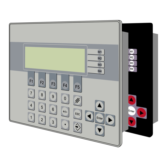
Page 9: Parts Named
Menu keys (assignment dependent on the actual window, row orientated) 3.3.2 Display The function of the display is dependent on the CompactController operating system and any software expansions loaded. There is a corresponding description in the ref- erence manual. GEL 8251... -
Page 10: Rear Side
DIP switch for terminating RS 422/485 Connection serial interfaces RS 232/422/485 (connector C1) Connection digital and analogue outputs and LED status indicators (terminal strips A1–3) Connection digital inputs and LED status indicators (terminal strip E1–3) Studs for control panel mounting GEL 8251... -
Page 11: Assembly
(are captive in the cover) and disconnect all connectors. After refitting the cover first press on the knurled screws and then tighten them. Remove the 6 nuts on the M4 studs on the CompactController and remove the device. GEL 8251... -
Page 12: Module Installation
Ensure that all pins on the module edge connectors are sitting correctly in the related housing connector. Communication with the extension modules is via a PLC program using CoDeSys function blocks provided. The basic configuration is undertaken using various system parameters (→ reference manual). GEL 8251... -
Page 13: Connections
● Lay signal cables and control cables physically separate from power cables ● If there are potential differences between the earth connections for the machine and electronics, or if such differences occur, ensure by means of appropriate measures GEL 8251... -
Page 14: Connector Coding
Do not disconnect any connectors or any screen connection while the device is switched on. Connector coding 9 10 11 9 10 11 9 10 11 GEL 8251... -
Page 15: Overview
GND (E4) DE2.8 DE4.1 DE4.2 GND (E3) DE4.3 DE3.1 DE4.4 DE3.2 DE4.5 DE3.3 DE4.6 DE3.4 DE4.7 DE3.5 DE4.8 DE3.6 GND (Z) DE3.7 DE3.8 24 VDC 24 VDC (Z) RS 422/485 COM 2 COM 1 COM 1 RS 422/485 GEL 8251... -
Page 16: Power Supply V
19 - 30 VDC internal If only a single power source is used to supply the controller and encoders, the related terminals 3 and 4 as well as 1 and 2 must be connected together as shown dotted in the figure. GEL 8251... -
Page 17: Serial Interfaces C1
COM 1 Peripherals RS 422 / RS 485 * RS 485 On the usage of RS 485, the connections 6 and 7 as well as 8 and 9 must be connected using solder jumpers (shown dotted in the figure). GEL 8251... -
Page 18: Can Bus C2
Switch in ON position. The termi- nating resistance is approx. 120 Ω CAN1 CAN2 The CAN buses have the same earth potential as the other serial interfaces (connector C1). CAN Client Controller CANx_H CANx_L GND (C) CAN1, CAN2 x = 1, 2 GEL 8251... -
Page 19: Encoder Inputs Z1-3
+5/24 V /SSI Data B SSI en- Ref_N coder B /Ref_N Clock Clock +24 VDC out Data 24 V Data +5 VDC out Z1 1 4 max. 0.6 A Z2 2 5 GND (Z) +5/24 V Z3 3 6 GEL 8251... -
Page 20: Digital Inputs E1-4
The signal state on the 6 (E1) or 8 (E2 to E4) digital inputs is indicated by green light emitting diodes underneath the related terminal (on ≙ high). E1/2/3/4 Controller Control DEx.1 DEx.2 DEx.3 DEx.4 DEx.5 DEx.6 DEx.7 DEx.8 +24 V GND (Ex) (Ex) GEL 8251... -
Page 21: Analogue Inputs E6
/AE1.1...3 1/3/5 To stabilise the differential input it is recommended to connect the earth for the external sensor supply to the analogue earth on the controller: – terminal strip E5, terminals 1/3/5/7 – terminal strips A1–3, terminal 2 GEL 8251... -
Page 22: 5.10 Pt100 Analogue Inputs E5
-40 °C to +215 °C. The measuring range is converted internally to a digital value range from 0 to 255 (1 byte). The inputs 1/3/5/7 are connected together (earth). Controller + 5 V (U PT100 AE1.4...7 /AE1.4...7 (AE1.4...7) GEL 8251... -
Page 23: Digital And Analogue Outputs A1-3
(on ≙ high). Digital: A1/2/3 Controller External control 24 VDC Ext. +24 V DAx.1 DAx.2 DAx.3 30 mA GND (Ax) (Ax) DAx.4 DAx.5 500 mA (Ax) Analog: Controller Drive A1/2/3 amplifier AA1/2/3 10 k (Q10+Q20+Q30) GEL 8251... -
Page 24: Commissioning
9,600 baud (to be set via the connector icon). Other communication parameters: 8 data bits, even parity, 1 stop bit, no control GEL 8251... - Page 25 After confirming using OK, the program will prompt you to reset the device. Switch off the CompactController. Press the miniature button in the housing as per the following figure using a non- metallic object (e.g. match) and switch the device back on. GEL 8251...
- Page 26 ‘.b86’. This file can be written back again at any time – as explained above (backup function). The name of the file is generated automatically by the option selected, but can be changed if necessary. GEL 8251...
- Page 27 The memory area to be uploaded is defined using the Upload options (click connector icon). Using the magnifying glass icon a comparison can be made between the data displayed and the data in the CompactController. A corresponding upload process is started for this purpose. GEL 8251...
-
Page 28: Technical Data
IP 65, rear side: IP 20 Operating temperature -20 °C to +70 °C Storage temperature -30 °C to +70 °C Relative humidity of air 95 %, non-condensing Vibration resistance (IEC 60068, 2-6) 20 m/s , 9 to 50 Hz GEL 8251... -
Page 29: Dimensional Drawing
112.5 16.8 20.8 23.2 22.8 When using the device in residential areas or in commercial or industrial environments the requirements as to electromagnetic emission defined in EN 61000-6-3 can be complied with by applying additional shieldings and filters. GEL 8251... - Page 30 7 Technical data Lenord + Bauer Dimensional drawing With horizontal cable outlet (option) 112.5 112.5 16.8 20.8 GEL 8251...
Need help?
Do you have a question about the GEL 8251 and is the answer not in the manual?
Questions and answers