Table of Contents
Advertisement
Quick Links
Advertisement
Table of Contents

Summary of Contents for Directechs PEAKROBOTICS KX-2
- Page 1 User’s Manual PSM-126 Rev. 3 3/3/2021 Author: Patrick Moreland Modified By: Patrick Moreland Approved By: Patrick Moreland Peak Robotics, Inc. 4747 Centennial Blvd; Colorado Springs, CO 80919 Ph 719.598.3555, www.peakrobotics.com Printed: 3/3/2021...
-
Page 3: Table Of Contents
KX-2 Robot - User’s Manual Table of Contents Disclaimer................................1 Contact Info ................................1 Introduction ............................... 2 Warnings ..............................3 Safety Precautions ............................. 5 Compliance with Standards ........................7 Contents and Packaging Instructions ......................8 Product Description ..........................11 Specifications ............................14 Gripper ..............................20 Electrical Description ..........................26 10.0... -
Page 4: Disclaimer
KX-2 Robot – User’s Manual Peak Robotics, Inc. 4747 Centennial Blvd; Colorado Springs, CO 80919 Ph 719.598.3555, www.peakrobotics.com Printed: 3/3/2021 Page 1... -
Page 5: Introduction
KX-2 Robot – User’s Manual 1.0 Introduction 1.1 Thank you for purchasing a KX-2 Laboratory Robot. This robot was developed specifically for challenging laboratory environments. It incorporates proven technology that was developed for the demanding semiconductor industry. 1.2 Reference Guide: This manual is intended to be a reference guide for the engineer and maintenance technician responsible for installation and maintenance of the KX-2 Robot. -
Page 6: Warnings
KX-2 Robot – User’s Manual 2.0 Warnings 2.1 Symbols: The following symbols are used in this manual. This icon accompanies text and/or other international symbols dealing with hazards to personnel. When present, it indicates that a potential hazard to personal safety exists if information stated within the "WARNING" paragraph is not adhered to or procedures are executed incorrectly. - Page 7 KX-2 Robot – User’s Manual 2.2 Installation: This product is sold as a component to be installed in a complete system using good engineering practices. Care must be taken by the system integrator to ensure that this product, as well as the other products in the system, are installed and used in a safe manner according to local and international safety laws and regulations, as well as any safety standards required by the end-user.
-
Page 8: Safety Precautions
KX-2 Robot – User’s Manual 3.0 Safety Precautions 3.1 General Precaution: The KX-2 robot operates under computer control. As with most computer- controlled and robotic devices, there is always the potential for injury or damage from moving components whenever the device is in motion. Warning: Never reach into the robot’s working envelope when the unit is moving. - Page 9 KX-2 Robot – User’s Manual 3.5 Teaching the Robot: The robot software has no provisions for avoiding surrounding equipment automatically. The robot merely executes the commands sent to it. Note: It is the responsibility of the teaching operator/programmer to create sequences that avoid obstacles.
-
Page 10: Compliance With Standards
KX-2 Robot – User’s Manual 4.0 Compliance with Standards 4.1 The KX-2 robot complies with the following standards: Standard Description CISPR11/FCC Class B Emission Standard for Industrial Environments (EMC) EMC Directive 2014/30/EU IEC 61326-1:2012, Electrical Equipment for Measurement, Control and Laboratory Use (EMC) IEC 61010-1:2016 Safety Requirements for Laboratory Equipment ISO 10218-1:2011... -
Page 11: Contents And Packaging Instructions
KX-2 Robot – User’s Manual 5.0 Contents and Packaging Instructions 5.1 Package Contents • Robot in plastic bag • Power Supply & AC Power Cord • E-Stop with Cable • USB Cable – Robot to User PC Connection • Barcode Reader Cable – Robot to User PC Connection •... - Page 12 KX-2 Robot – User’s Manual Step 3) Remove the two large pieces of foam that cover the two ends of the robot. Step 4) With the help of an assistant, lift the robot out of the box Lift via the two ends of the robot. Rotate the robot so that the arm is pointing upward.
- Page 13 KX-2 Robot – User’s Manual Step 7) Detach the Robot Mount Plate from the bottom of the robot by removing the three screws and flat washers securing it to the Shoulder. Step 8) Attach the Robot Mount Plate to the table in the desired location using the three included M6 flathead screws.
-
Page 14: Product Description
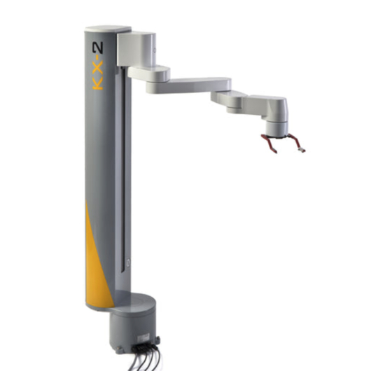
KX-2 Robot – User’s Manual 6.0 Product Description 6.1 Description: The KX-2 is a tabletop cylindrical robot designed for laboratory and light industrial applications. 6.2 Technology: The robot has four axes of motion and incorporates a combination zero-backlash harmonic drive gearboxes and belt drives driven by DC servomotors. Motion control is accomplished via true absolute encoders and distributed motor drives. - Page 15 KX-2 Robot – User’s Manual 6.6 User Inputs/Outputs: There are three digital inputs, two analog inputs, and three digital outputs available at base of the robot. These are described in more detail later in this document. 6.7 Internal Motor Drives: All joints and gripper are servo-driven with drives mounted inside the robot next to each motor.
- Page 16 KX-2 Robot – User’s Manual Serial Number Tag Peak Robotics, Inc. 4747 Centennial Blvd; Colorado Springs, CO 80919 Ph 719.598.3555, www.peakrobotics.com Printed: 3/3/2021 Page 13...
-
Page 17: Specifications
KX-2 Robot – User’s Manual 7.0 Specifications 7.1 General Specifications Max Payload 500g (1.1lb) Radial Stroke 525mm (20.7in) Radial Reach 787mm (31in) w/Side-Grip Fingers, 677mm (26.6in) to Wrist Center Radial Compactness 190mm (7.47in) with Gripper Facing Inward Travel: Shoulder 360° Unlimited 500mm (19.69in) or 750mm (29.53in) Elbow 525mm (20.7in) - Page 18 KX-2 Robot – User’s Manual Encoders Magnetic Absolute on robot joints, Incremental on gripper Teaching Drag-to-teach-point, one-touch teach button on robot Gripper Options Top-Grip, Side-Grip, Side-Grip-Portrait-Jog, Custom PC Interface USB 2.0 7.2 Environmental Conditions Condition Limits Operating Ambient Temperature 5° to 40°C (41° to 104°F) Storage Temperature -20°...
- Page 19 KX-2 Robot – User’s Manual 7.4 Robot Dimensions, Top View: Peak Robotics, Inc. 4747 Centennial Blvd; Colorado Springs, CO 80919 Ph 719.598.3555, www.peakrobotics.com Printed: 3/3/2021 Page 16...
- Page 20 KX-2 Robot – User’s Manual 7.5 Robot Dimensions, Side View (KX-2 500 shown): Peak Robotics, Inc. 4747 Centennial Blvd; Colorado Springs, CO 80919 Ph 719.598.3555, www.peakrobotics.com Printed: 3/3/2021 Page 17...
- Page 21 KX-2 Robot – User’s Manual 7.6 Power Supply Dimensions: Peak Robotics, Inc. 4747 Centennial Blvd; Colorado Springs, CO 80919 Ph 719.598.3555, www.peakrobotics.com Printed: 3/3/2021 Page 18...
- Page 22 KX-2 Robot – User’s Manual 7.7 Axis Naming Definitions: Name Designation Description “S” Axis 1 Shoulder Motor, Shoulder Rotate “Z” Axis 2 Z Motor, Vertical Axis “E” Axis 3 Elbow Motor, Arm Extend “W” Axis 4 Wrist Motor, Wrist Rotate KX-2 Axis Naming Definitions Peak Robotics, Inc.
-
Page 23: Gripper
KX-2 Robot – User’s Manual 8.0 Gripper 8.1 Description: The base model KX-2 robot comes standard with an electric gripper. The robot can be operated without a gripper, if need be. It is not possible to route a pneumatic hose through the KX-2, so a pneumatic gripper is not an option. - Page 24 KX-2 Robot – User’s Manual 8.5 A forward-facing retro-reflective optical sensor is located on the front of the gripper. This sensor is used for counting the number of plates in a FILO stack. Due to location of this sensor, it is not used for determining the presence/absence of a plate in the gripper.
- Page 25 KX-2 Robot – User’s Manual 8.7 Side-Grip: Side-grip Universal, 110mm Offset (grips either portrait or landscape). This gripper finger style is used typically with Side-Grip Landscape FILO Stacks and Random-Access Portrait & Landscape Hotels, as shown below. SGF Side-Grip Fingers SS-SL Stack HR-SU Hotel Peak Robotics, Inc.
- Page 26 KX-2 Robot – User’s Manual 8.8 Side-Grip Portrait-Jog: Side-grip Universal, 116mm Offset (grips either portrait or landscape). This gripper finger style is used typically with Side-Grip Portrait FILO Stacks, as shown below (jogged fingers are required for clearing the stack uprights). SGJF Side-Grip Portrait-Jog Fingers SS-SP Stack Peak Robotics, Inc.
- Page 27 KX-2 Robot – User’s Manual 8.9 Side-Grip Sensor Adjustment: The plate presence sensor for the Side-Grip and Side-Grip Portrait-Jog grippers is located under the gripper housing as shown here. Depending on the type of microplate being used, the sensor may need to be adjusted per the table shown below. The sensor must be detached from the gripper to access the adjustment screw.
- Page 28 KX-2 Robot – User’s Manual 8.10 Gripping on Skirt: All KX-2 grippers are designed to grip plates with or without lids; however, in some installations, it may be advantageous to grip very low on the plate as shown below. Gripping Plate on Skirt - Low Gripping Plate above Skirt - Normal Peak Robotics, Inc.
-
Page 29: Electrical Description
KX-2 Robot – User’s Manual 9.0 Electrical Description 9.1 Power: The robot is powered by standard residential single-phase AC power (see Specifications section). The AC power cord plugs into the power supply box. The power supply box contains a 57VDC power supply and a 24VDC power supply. A cable with a 13-pin mini-DIN connector connects the power supply box to the robot and supplies the robot with DC power used by the motor drives, sensors, and indicator lights. - Page 30 KX-2 Robot – User’s Manual 9.3 Emergency Stop Wiring: A button for stopping the robot in emergency situations is plugged into the robot. Actuating the Intelligent E-Stop circuitry by pressing the E-Stop button stops the robot but keeps the motor drive logic circuits powered. Restarting the robot after an E-Stop requires a deliberate input by the operator on the controlling computer.
- Page 31 KX-2 Robot – User’s Manual 9.5 Status LED: If the E-Stop button is popped up, power is applied to the robot, and no Shoulder drive errors are present, then the Drive Status LED located on the Shoulder connector panel should be green. If the LED is red, then either the E-Stop button is pressed or disconnected, or a Shoulder drive error is present.
- Page 32 KX-2 Robot – User’s Manual 9.6 Power LED: If AC power is connected to the power supply box and the AC power switch is in the “on” position, the blue LED powered by 24V should be on. If this LED is not on, then the fuses inside the power entry module may be blown.
- Page 33 KX-2 Robot – User’s Manual 9.7 Controlling PC: A standard PC must be supplied to control the robot. The PC must be equipped with Windows 7 or higher and must have two USB 2.0 ports available for main PC communication as well as the supplied USB/Serial adapter for the barcode reader. 9.8 DLL: The robot control software is a universal .NET 4.0 DLL.
-
Page 34: Installation And Setup
KX-2 Robot – User’s Manual 10.0 Installation and Setup 10.1 Setup: The procedures described in this section are used to install and configure the robot. These procedures, or a portion of them, may need to be followed whenever any of the following occur: •... - Page 35 KX-2 Robot – User’s Manual 10.2.2 Mounting Surface: The recommended mounting surface for the robot and all devices is 10mm (3/8”) thick (minimum) aluminum tooling plate. The aluminum can be powder coated or epoxy coated to resist most chemicals. If plastic must be used, a minimum thickness of 25mm (1”) is highly recommended;...
- Page 36 KX-2 Robot – User’s Manual 10.2.4 Mounting Screws: There is only a small amount of clearance in the screw holes, so it is critical that the anchoring threaded holes be drilled and tapped accurately and perpendicular to the mounting surface. If a milling machine is not available for this purpose, it is recommended that the Robot Mount Plate be used as a jig for marking the mounting-hole locations with a transfer punch.
- Page 37 KX-2 Robot – User’s Manual 10.2.5 Mounting the Robot to the Table: 1) Attach the Robot Mount Plate to the table with three M6x18 or 1/4x3/4” flat-head cap screws. Choose the desired orientation for optimal cable routing. If the screw holes in the table are threaded, then ensure the screws are long enough to have at least 9mm (3/8”) of thread engagement.
- Page 38 KX-2 Robot – User’s Manual 5) Have an assistant hold the robot so that it does not tip over. Extending the arm about halfway will help to stabilize the robot. Install three M6x16 SHCS (each with a flat washer positioned against the head and with the rounded edge facing downward) through the mounting ears on the bottom of the robot, and thread them into the Robot Mount Plate.
- Page 39 KX-2 Robot – User’s Manual • Unplug the black ribbon cable from the blue connector on the PCB. • Use a 10mm open-end wrench to loosen the two M6x25 Hex Head screws securing the Arm to the Z Axis. Loosen each screw about half a turn. •...
- Page 40 KX-2 Robot – User’s Manual • Set the Arm assembly down on a soft surface. Peak Robotics, Inc. 4747 Centennial Blvd; Colorado Springs, CO 80919 Ph 719.598.3555, www.peakrobotics.com Printed: 3/3/2021 Page 37...
- Page 41 KX-2 Robot – User’s Manual • Remove the six M3x6 SHCS screws from the large cover on the back of the Z Axis. Remove the two top screws last. This will help support the cover while the screws are being removed. Remove the cover and set on a soft surface.
- Page 42 KX-2 Robot – User’s Manual • Remove the two M5x16 FHCS screws from the smaller section of the counterweight on the right side. Slide the smaller section of the counterweight upward and out of the Z Axis. • Remove the four M5x30 FHCS screws from the remaining larger section of the counterweight.
- Page 43 KX-2 Robot – User’s Manual • The weight of the robot is reduced significantly at this point and can be lifted onto a table by one person. • Assembly is the reverse of disassembly. Apply Loctite 242 to all removed screws prior to reinstallation.
- Page 44 KX-2 Robot – User’s Manual 10.4 Cable Connections: 10.4.1 The power supply box must be positioned within 2.75m (9ft) of the robot shoulder due to cable length limitations (EMC). Make sure AC power is not connected to the power supply box before proceeding. 10.4.2 Plug the DC power cable into the recessed round connector in the Shoulder connector panel with the notches lined up.
- Page 45 KX-2 Robot – User’s Manual 10.4.6 Connect the other end of the Barcode Reader cable to the supplied Prolific USB/Serial adapter. Tighten thumb screws lightly. Plug the adapter into an available USB 2.0 port on the PC. 10.4.7 Plug the AC power cord (Volex 17661) into the power supply box. 10.4.8 Plug the other end of the AC power cord into a standard grounded North American residential 110V outlet.
- Page 46 KX-2 Robot – User’s Manual 10.4.9 Apply AC power to the power supply box by flipping the switch on the AC power entry module to the ‘I’ position. The blue power indicator LED on the box should light up. The Shoulder drive status LED should also light up. It should be red initially and should then change to green after a few seconds.
- Page 47 KX-2 Robot – User’s Manual 10.5 Software Installation: 10.5.1 The following items are included on the USB memory stick shipped with the robot: • KX2 Robot Control DLL – Teach Pendant / KX2 Robot Control DLL vX.X.X Setup.zip • CAN-USB Adapter Driver / Peak-System_Driver_Setup.zip 10.5.2 DLL: Extract the file named “KX2 Robot Control DLL vX.X.X Setup.zip”.
- Page 48 KX-2 Robot – User’s Manual 10.5.8 Open the Options window by clicking on the gear icon in the upper right corner of the window. Click Here 10.5.9 Open the “Communication Settings” tab, click the “CAN Device” list and verify the desired device is selected.
- Page 49 KX-2 Robot – User’s Manual 10.6 Initializing the Robot: 10.6.1 Make sure the robot is clear of any obstructions before initializing. All four axes of the robot can be moved away from obstructions carefully by hand prior to powering up. 10.6.2 Boot up the controlling computer.
-
Page 50: System Software
KX-2 Robot – User’s Manual 11.0 System Software 11.1 The robot is controlled by a universal .NET 4.0 DLL that provides the end-user with a list of general robot commands (initialize, move to teach point, run sequence, etc.), and converts these general commands into individual coordinated axis commands and sends them to the robot. -
Page 51: Teach Pendant
KX-2 Robot – User’s Manual 12.0 Teach Pendant 12.1 Multiple robot position orientations can be named and saved. These saved orientations are called “Teach Points” and are used to create robot sequences. Important Note: It is imperative to use a logical and methodical approach to teaching the robot to ensure long- term operation without repeatability problems. - Page 52 KX-2 Robot – User’s Manual 12.5 Teach Points Tab: This tab displays the following window: Teach Pendant Window, “Teach Points” Tab 12.6 The Teach Points Tab provides the ability to perform the following operations: 12.6.1 Teach Points: Use the following procedure to create a Teach Point: Select the desired Teach Point number in the “Teach Points”...
- Page 53 KX-2 Robot – User’s Manual Clearing the “Name” field will erase a previously taught Teach 12.6.1.5 Point. The Teach Point is then cleared from memory. 12.6.1.6 The axis positions associated with a Teach Point can be modified manually by entering the desired values into the Shoulder, Z Axis, Elbow, and Wrist columns.
- Page 54 KX-2 Robot – User’s Manual 12.6.2.5 To move only one axis to a desired position, right-click on one of the position textboxes, and select ‘Move Single Axis’ in the context menu that appears. Motion Mode: If “Joint” is selected, each joint will move the shortest 12.6.2.6 distance when executing a move.
- Page 55 KX-2 Robot – User’s Manual 12.7 Jog Controls Tab: This tab displays the following window: Teach Pendant Window, “Jog Controls” Tab 12.7.1 The “Jog Controls” tab provides the ability to perform various jogging operations as detailed below. Clicking the corresponding button (arrow) in the “Jog Controls” window will jog the robot: Select the desired “Motion”...
- Page 56 KX-2 Robot – User’s Manual • Joint—Individual joints will be jogged independently in a joint coordinate system, as shown in the image of the robot next to the jog controls. • Cartesian—The end of the arm will move along a linear path.
- Page 57 KX-2 Robot – User’s Manual World Reference Frame, Cartesian Coordinates, Top View Tool Reference Frame, Cartesian Coordinates, Top View Peak Robotics, Inc. 4747 Centennial Blvd; Colorado Springs, CO 80919 Ph 719.598.3555, www.peakrobotics.com Printed: 3/3/2021 Page 54...
- Page 58 KX-2 Robot – User’s Manual 12.7.1.7 Enable Joystick—Check this box to allow the use of a game controller (not provided) for jogging the robot. Use of a game controller is described later. 12.7.1.8 Enable Teach Button—Check this box to allow the use of the teach button located on the front of the Elbow housing.
- Page 59 KX-2 Robot – User’s Manual 12.8 Inputs/Outputs Tab: This tab displays the following window. Teach Pendant Window, “Inputs/Outputs” Tab 12.8.1 The Inputs/Outputs Tab provides the ability to perform the following operations: Digital Inputs: Select the desired input in the “Select Input:” pull- 12.8.1.1 down.
- Page 60 KX-2 Robot – User’s Manual 12.8.1.4 Gripper: If the robot is equipped with a gripper, then the Gripper controls will be visible. • The “Velocity %” box can be used to adjust the velocity for all gripper controls below. • The “Open”...
- Page 61 KX-2 Robot – User’s Manual 12.9 Motion Rules Tab: This tab displays the following window: Teach Pendant Window, “Motion Rules” Tab 12.9.1 The “Motion Rules” tab is used for defining pairs of teach points between which the robot can move safely. Once motion rules are defined, and the “Enable” box is checked, motion between two teach points not in the “Rules”...
- Page 62 KX-2 Robot – User’s Manual 12.10 The drop-down menus at the top left corner of the Teach Pendant window contain the following commands: 12.10.1 File Menu: Teach Pendant File Drop-Down Menu “Backup Registry Settings To File” will display a file-browsing 12.10.1.1 window for creating a text file that contains all of the settings that are stored in the Windows Registry by the KX-2 software.
- Page 63 KX-2 Robot – User’s Manual Select Configuration Window • Windows Registry—This is the standard setting. Select “.Default” from the “Configuration” list to use the standard “HKEY_CURRENT_USER\Software\VB and VBA Program Settings\KX2 Robot Control\” location in the Windows Registry for software settings storage.
- Page 64 KX-2 Robot – User’s Manual Shortcut Properties “Exit” will close the Teach Pendant window. 12.10.1.4 Peak Robotics, Inc. 4747 Centennial Blvd; Colorado Springs, CO 80919 Ph 719.598.3555, www.peakrobotics.com Printed: 3/3/2021 Page 61...
- Page 65 KX-2 Robot – User’s Manual 12.10.2 Tools Menu: Teach Pendant Tools Drop-Down Menu “Terminal...” opens a window that is used for communicating 12.10.1.1 directly with the motor drives using two-letter commands. Commands are constructed from the following elements: • Two-letter command (e.g., PX for position, MS for motion status, EC for error code) •...
- Page 66 KX-2 Robot – User’s Manual Teach Pendant Tools/Terminal Window 12.10.2.2 Joystick Setup displays a window for testing and configuring a joystick that can be used for jogging the robot axes remotely. This item will only be visible if the “Joystick” option is selected under Options…/Communication Settings.
- Page 67 KX-2 Robot – User’s Manual 12.11 Disable Motors—Click the Unlock icon at the top of the Teach Pendant to allow positioning of the arm by hand. The motors will be disabled. The encoders are still powered and will keep track of the robot position as it is moved. Click the icon again to re-enable the motors.
- Page 68 KX-2 Robot – User’s Manual Sequence Editor – Clicking the ‘running man’ icon at the top of the Teach Pendant 12.12 will open the following window, which can be used to create robot sequences. Click Here Sequence Editor Window Peak Robotics, Inc. 4747 Centennial Blvd;...
- Page 69 KX-2 Robot – User’s Manual 12.12.1 Creating a Sequence • Click the “Add Sequence” button underneath the “Sequence” list. Enter the desired name in the “Add Sequence” window. • Select the “END” line in the “Operations box. • Click the “Add Operation” button to add an operation to the sequence. A default operation will be added.
- Page 70 KX-2 Robot – User’s Manual the sequence will loop indefinitely. Enter a numeric value in the box to specify a finite number of loops. 12.12.4 Editing a Sequence • An existing sequence can be renamed, copied, or deleted using the buttons directly underneath the Sequence list.
- Page 71 KX-2 Robot – User’s Manual AutoTeach – Clicking the ‘graduation cap’ icon opens a window that creates teach 12.13 points automatically each time the button on the top of the arm is pressed. Click Here AutoTeach Window 12.13.1 When the AutoTeach window is opened, the motors are disabled so the robot can be moved by hand.
- Page 72 KX-2 Robot – User’s Manual Options – Clicking the ‘gear’ icon opens the following window where robot settings 12.14 can be modified. Click Here 12.14.1 The first Options tab is “File Locations”. Options Window, File Locations Tab • Teach Point File—When KX2 Robot Control DLL is installed, a blank Teach Point file will be placed in the C:\ProgramData\Peak Analysis &...
- Page 73 KX-2 Robot – User’s Manual 12.14.2 The second Options tab is “Communication Settings”. Options Window, Communication Settings Tab • CAN Device—The Device ID of the CAN/USB adapter inside the robot is specified here. The ID of the adapter may need to be changed if multiple robots are connected to the same PC.
- Page 74 KX-2 Robot – User’s Manual • Default Gripper State —Check this option to have the gripper either open or close during initialization. To leave the gripper in its current state, uncheck this option. Setting the default position to ‘Closed’ helps reduce the chance of dropping a plate that was left in the gripper from a previous operation.
- Page 75 KX-2 Robot – User’s Manual 12.14.3 The third Options tab is “Miscellaneous”. Options Window, Miscellaneous Tab • Warning Before Move—Check this option to have the buzzer beep and the blue indicator light flash prior to moving after an idle period longer than the time specified in the “Idle Time”...
- Page 76 KX-2 Robot – User’s Manual 12.14.4 The fourth Options tab is “Mail Settings”. Options Window, Mail Settings Tab • Send Email Upon Robot Error—This option sends an email to the “To Address” each time the robot generates an error. A POP3 email account is required. •...
- Page 77 KX-2 Robot – User’s Manual 12.15 Help Menu: About…—A window will open, displaying the current version and release date of GX Robot Control. Help/About… Window Peak Robotics, Inc. 4747 Centennial Blvd; Colorado Springs, CO 80919 Ph 719.598.3555, www.peakrobotics.com Printed: 3/3/2021 Page 74...
- Page 78 KX-2 Robot – User’s Manual 12.16 Joystick Control 12.16.1 A game controller (Logitech Gamepad F310, P/N 940-000110 recommended) can be used to control the robot. Most Windows-compatible joysticks or game controllers can be configured to work with the KX-2 robot. 12.16.2 To enable Joystick control, open the Teach Pendant, click the "Options"...
- Page 79 KX-2 Robot – User’s Manual 12.16.5 The default mapping of robot functions to the joystick controls are as follows: Increment Gripper Decrease Close Gripper Increment Open Increase Continuous/Incremental Motion Joint/Cartesian Mode Elbow/Y+ Wrist- Shoulder/X+ Wrist+ Shoulder/X- Elbow/Y- Peak Robotics, Inc. 4747 Centennial Blvd;...
- Page 80 KX-2 Robot – User’s Manual 12.16.6 To remap robot functions to different joystick controls, go to the “Tools” menu, and select “Joystick Setup…” The following window will open. Joystick Setup – Settings Tab 12.16.6.1 Each robot function can be controlled either by a button, a joystick, or a POV (point of view) control.
- Page 81 KX-2 Robot – User’s Manual This is especially useful for the Shoulder/X directions since the positive Shoulder direction causes the robot to move in the opposite direction from the positive X direction. 12.16.7 To monitor the states of the various joystick controls, click on the “Controls” tab. Joystick Settings - Controls 12.10.1.1 As the joystick controls are manipulated, their current values will...
-
Page 82: Teaching Routine
KX-2 Robot – User’s Manual 13.0 Teaching Routine 13.1 The following instructional guidelines assume that the user’s sequence will be using microtiter plates, although the same techniques apply to almost any installation. Important Note: Most non-repeatability problems with the installed robot can be traced to either a non-rigid installation or improper teaching methods. - Page 83 KX-2 Robot – User’s Manual from this point forward must be done with the Teach Plate gripped in the same set of indentations. It is recommended that a felt-tip pen be used to mark the indentations being used. 1) Insert the Teach Plate into the robot gripper as follows. Use the Teach Pendant to open the gripper by clicking the “Open”...
- Page 84 KX-2 Robot – User’s Manual 13.6 Teaching Plate Stacks: 13.6.1 The KX-2 Robot is often used in conjunction with optional plate stacks. This type of plate storage is a first-in-last-out (FILO) arrangement where plates are placed directly on top of each other. When a plate is removed, the plate on top of the stack must be removed first.
- Page 85 KX-2 Robot – User’s Manual method definitions in the Software manual). Note: When moving to and from stacks, the robot must be at least as high as the top teach point of the stack plus the “Stack Top Clearance” value. This is to avoid the possibility of the robot being commanded to move to above a stack starting from too low of a position, which would cause the robot to hit the top of the stack on its way there.
- Page 86 KX-2 Robot – User’s Manual 13.7.3 Determine the “Lift Height” value, which is the vertical distance the plate must be lifted to clear the pocket in the hotel shelf. Select a value that sets the clearance between the bottom of the plate and the top of the shelf equal to the clearance between the tops of the gripper fingers and the underside of the next shelf up.
- Page 87 KX-2 Robot – User’s Manual 13.9 Unlimited Rotation 13.9.1 The Shoulder and Wrist of the KX2 robot have unlimited rotation. This allows the robot to move the shortest distance between two points without the need to unwind the joints. 13.9.2 In some cases, it may be desired to have one or more joints rotate the long way around.
-
Page 88: User I/O & Emergency Stop
KX-2 Robot – User’s Manual 14.0 User I/O & Emergency Stop 14.1 The robot contains digital inputs, analog inputs, and digital outputs that are available to the user, and are controlled through the robot control software (DLL). They can be monitored and toggled using the Teach Pendant Inputs/Outputs tab described in the previous sections. - Page 89 KX-2 Robot – User’s Manual 14.4 Emergency Stop 14.4.1 The robot is equipped with an emergency stop button that, when pressed, will cause the robot to decelerate to a controlled stop. Power is then removed from the motors after a 750ms delay. Power will not be restored to the motors until after the emergency stop button is popped back up by twisting it clockwise, and an Initialize command has been sent via the software.
- Page 90 KX-2 Robot – User’s Manual 14.4.11 When the emergency stop button is pressed, a signal is sent to the robot via digital inputs 5 and 6 on the shoulder motor drive, which initiates a controlled deceleration of all motors. The safety rated STO1 and STO2 motor drive inputs receive a delayed signal 750 milliseconds later, and power is removed from the motors.
- Page 91 KX-2 Robot – User’s Manual 14.4.16 The interlock(s) can be spliced into the middle of the emergency stop button cable by cutting the cable in the middle. 14.4.17 Any interlocks that are added to the system must be evaluated, according to ISO 13849:1-2015, to ensure that PL=d and Category 3 ratings are preserved.
-
Page 92: Troubleshooting & Replacement
KX-2 Robot – User’s Manual 15.0 Troubleshooting & Replacement 15.1 Important Notes: 15.1.1 A thorough understanding of the operation of the robot is required to perform a proper setup. 15.1.2 The following information is meant as a general guide only. Common sense must be applied to adjustments or when troubleshooting. - Page 93 KX-2 Robot – User’s Manual 15.6.3 Old software version being used with newer motor & controller firmware versions. Install the latest version of robot software. 15.6.4 Slip ring failure. Consult factory. 15.6.5 Robot internal component or wiring degradation. Consult factory. 15.6.6 In some cases, it can be helpful to use a video camera to capture robot errors that happen during motion.
-
Page 94: Periodic Maintenance
KX-2 Robot – User’s Manual 16.0 Periodic Maintenance 16.1 Periodic maintenance should be performed every time the Z axis has completed the equivalent of 1000 kilometers linear travel. Maintenance should be performed at least every two years even if 1000 kilometers of linear travel has not been reached. 16.1.1 The software logs the total accumulated travel of each axis. - Page 95 KX-2 Robot – User’s Manual 16.1.8 Use Castrol Tribol GR 100-2 PD grease (14-oz. cartridge is part number 157C88- 14OZ). Peak Robotics, Inc. 4747 Centennial Blvd; Colorado Springs, CO 80919 Ph 719.598.3555, www.peakrobotics.com Printed: 3/3/2021 Page 92...
- Page 96 KX-2 Robot – User’s Manual 16.1.9 Grease the Z Axis arm support bearing, as follows: • Raise the Z Axis to the top of its travel • Pop the round black plastic cap out of the access hole on the front of the Z housing.
- Page 97 KX-2 Robot – User’s Manual • Lower the Z Axis to the bottom of its travel. Extend the arm part way so that it doesn’t block the access hole. Zerk • Attach the grease pump to the zerk. The arm support bearing needs 1.4 cubic centimeters (0.05oz) of grease added to it at each maintenance interval.
- Page 98 KX-2 Robot – User’s Manual 16.1.10 Grease the Z Axis counterweight support bearing, as follows: • Remove the six M3x6 SHCS screws from the large cover on the back of the Z Axis. Remove the two top screws last. This will help support the cover while the screws are being removed.
- Page 99 KX-2 Robot – User’s Manual • The counterweight support bearing grease zerk is accessed via a hole in the counterweight. Zerk • Attach the grease pump to the zerk. The counterweight support bearing needs 0.4 cubic centimeters (0.014oz) of grease added to it at each maintenance interval.
- Page 100 KX-2 Robot – User’s Manual 16.2 Emergency Stop Maintenance 16.2.1 To maintain the rated safety level of the emergency stop function, the user shall perform a diagnostic test periodically, as follows: 1) With the emergency stop button popped up in its normal position, the Drive Status LED located on the Shoulder connector panel must be green.
- Page 101 KX-2 Robot – User’s Manual Revision History Revision Date Line Description 1/28/2020 Initial Release 7/27/2020 Robot shipped with both Side-Grip & Top-Grip fingers 8.5-6 Instructions for scanning a stack with Top-Grip fingers 3/3/2021 10.5.1 Added folder names in addition to file names Peak Robotics, Inc.
Need help?
Do you have a question about the PEAKROBOTICS KX-2 and is the answer not in the manual?
Questions and answers