Table of Contents
Advertisement
Owner's Manual
POWER
GLIDE
DOWN
OCTAVE
DC
USB
INPUTS
MOD 1
TEMPO
UP & DN
UP / DN
DOWN
UP
MODE
ON
EDIT
RIBBON
UP
CHORD
MAX
MIN
MIDI IN
MIDI OUT
MIDI THRU
CV / GATE
OUTPUTS
MOD 2
PITCH
GATE
MOD 1
MOD 2
ARPEGGIATOR
RATCHET
CHANCE
ORDER
1
1 32
58
RANDOM
2
1 16
54
CHORD
3
1 8
52
PHRASE
4
1 4
OFF
OCTAVE
DIVISION
LATCH
TRIPLET
SUSTAIN
EXPRESSION
SUSTAIN
L/MONO
OUTPUT
MAIN SY
BROWSE
FAVORITE
CLOCK
SAVE
SYSTEM
SETUP
GATE
62
INIT
66
70
75
RANDOM
SWING
TAP
SHIFT
TEMPO
Advertisement
Table of Contents

Related Manuals for ASM Polytouch HYDRASYNTH EXPLORER

Summary of Contents for ASM Polytouch HYDRASYNTH EXPLORER
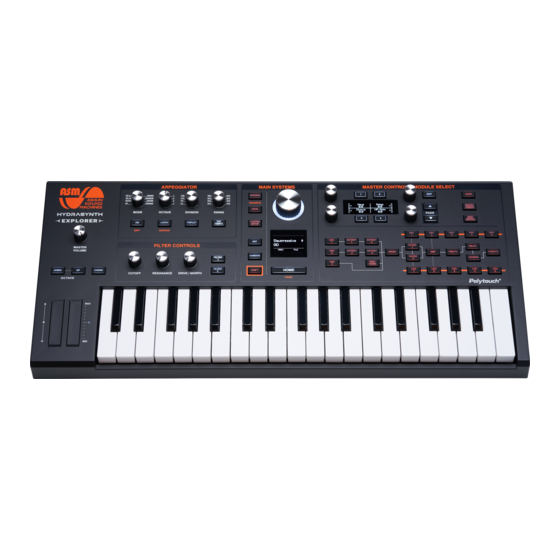
- Page 1 Owner’s Manual POWER MIDI IN MIDI OUT MIDI THRU EXPRESSION SUSTAIN L/MONO OUTPUT CV / GATE MAIN SY INPUTS OUTPUTS BROWSE FAVORITE MOD 1 MOD 2 PITCH GATE MOD 1 MOD 2 CLOCK SAVE ARPEGGIATOR SYSTEM SETUP TEMPO RATCHET CHANCE GATE UP &...
- Page 2 OCTAVE...
- Page 3 Special ThankS DESIGN & DIRECTION • Glen Darcey PRODUCT MANAGER • Dominic Au ENGINEERING • Chen Jiejun (engine) • Banner Xu (software) • Yang Zhihang (software) • Ye Haipeng (electronic) • Chen Si (electronic) • Luo Liangsheng (electronic) • Fu Jieming (Mechanics) •...
-
Page 4: Important Safety Instructions
iMpOrTanT SafeTy inSTrucTiOnS Save your ears! The product and its software, when used in combination with an amplifier, headphones or speakers, may be able to produce sound levels that could cause permanent hearing loss. DO NOT operate for long periods of time at a high level or at a level that is uncomfortable. If you encounter any hearing loss or ringing in the ears, please consult an audiologist. -
Page 5: Table Of Contents
cOnTenTS Master Control Section important Safety instructions ....17 EXIT button ....... . 18 Welcome to hydrasynth PAGE Up / Down buttons . - Page 6 LFOs 1 and 2 ....... 42 PW-ASM [Warp] ......28 LFO parameters: page 1 .
- Page 7 Using the Browser Microtonality ......54 ......66 The arpeggiator Section Browse parameters: page 1 .
- Page 8 MIDI: Page 10 ......74 Parameter send/receive options ... . 75 What’s a NRPN? .
-
Page 9: Welcome To Hydrasynth Explorer
WelcOMe TO hyDraSynTh explOrer! Everyone at Ashun Sound Machines would like to thank you for choosing one of our Hydrasynth instruments. We’re very proud of what we have created, and are confident they will take you into musical realms that have never been explored. Every aspect of these ground-breaking devices has been carefully considered, from the way the sounds are generated and processed, to the intuitive layout of the controls and displays. -
Page 10: Hardware
hardware • MIDI In/Out • USB type B port, class-compliant • CV/Gate and outputs for integration with modular synthesizers • Headphone output • Stereo 1/4” outputs (balanced) • Sustain pedal input (polarity-sensing) • LED Dim feature for darkened rooms • Kensington lock port •... -
Page 11: Quick Start Guide
Quick STarT GuiDe inside the Box Your Hydrasynth Explorer was carefully packed at the factory with the following items: • The Hydrasynth Explorer • This manual • The power supply (12VDC / ≥1A) Save your receipt! Ashun Sound Machines designed and constructed your Hydrasynth Explorer with extreme attention to detail. -
Page 12: Usb
MiDi Hydrasynth Explorer is a USB class-compliant The Hydrasynth Explorer has two 5-pin MIDI device, so there are no drivers to install. Just plug connectors to allow you to interface with other it into your computer and it will be available MIDI devices. -
Page 13: Tweaking The Sounds
There are words in orange letters under two of the buttons: EDIT and SUSTAIN. These are used with the [SHIFT] button to access their secondary functions. We’ll describe those and the other arpeggiator features in The Arpeggiator Section (p. 55). Tweaking the sounds The Right display provides information about what is happening and what the options are, no matter what you’re doing with the Hydrasynth. -
Page 14: Overview
OVerVieW The Hydrasynth Explorer represents a perfect balance of instant access, intuitive workflow, powerful features, and great sound, all with a single aim: to make the creation and performance of mind-blowing music easier and more fun. Top panel: hydrasynth explorer Section name Section name Master Volume... -
Page 15: Control Knobs
control knobs The Module Select buttons can be used as a quick way to set up a Mod Matrix route, too (hold one, press another). For information about that, see There are two knobs on either side of the Right Mod Matrix (p. -
Page 16: Main Systems
Main Systems Patch selection All Notes Off One of the major Sometimes MIDI signals are disrupted and a note functions of this becomes stuck. If that happens, hold [SHIFT] section is patch and press [HOME] to transmit an “All Notes Off” selection. -
Page 17: The Random Button
Initialize a Patch Left display shows “PATCHRND” after the first press, and after the second press a random If you want to build an entire patch from scratch, selection of values is pulled from other press [INIT] twice in a row. This will erase the patches. -
Page 18: Exit Button
MacrO aSSiGn button powerful Macro controls. For live performance or on-the-spot creativity, the Macros can kick everything into high gear. See Mastering the This Access button opens a page that is like a Macros (p. 58). hallway with eight doors, and behind each one is a lab that makes a powerful performance exiT button control called a Macro. -
Page 19: Filter Controls
filter controls Sweeping the filter frequency of a sound is a great way to heighten the emotional impact of the music. This is especially true during an arpeggio or a sequenced passage. Hydrasynth Explorer offers several controls for exactly this purpose. -
Page 20: Rear Panel
rear panel Section name Description CV / Gate connectors Interface with modular synthesizers Phones output Compatible with a wide range of impedance ratings Outputs Left (mono), Right (for stereo) Sustain pedal input Polarity sensing on startup MIDI connectors In, Out USB connector Type B for computer connection DC power connector... -
Page 21: Understanding The Modules
unDerSTanDinG The MODuleS The orange-lettered Access buttons select particular modules for editing, and can also be used to create new mod routes. They are arranged in the order of signal flow, from left to right: [Osc] > [Mixer] > [Filter] >... -
Page 22: Fx Group
fx group Voice module Rounding out each patch is a healthy array of Though it isn’t located in the Module Select effects processors, from pitch effects to spatial section, the Voice module has a significant impact emulations and much more. With these a raw on each patch. - Page 23 Modules that will When the Save button is held some of the Module buttons are lit. These are the ones that can be copied and pasted. There are limitations, of course; the parameters of an Oscillator cannot be pasted to one of the Filters, for example. Here’s a chart that shows the possible combinations.
-
Page 24: The Oscillator Group
The OScillaTOr GrOup Oscillators are the foundation of a patch. They generate the most basic component of the sound, which is then shaped by other components such as Mutants, Filters, Envelopes, etc. Hydrasynth Explorer has 3 oscillators per voice. Oscillators 1 and 2 can operate in two different modes: Single and WaveScan. -
Page 25: Wavescan Mode
WaveScan mode This mode offers all of the same waveforms found in Single mode, but then allows you to select up to eight of them in a Wavelist. WaveScan will morph gradually between the positions in the Wavelist, using an LFO or some other source through the Mod Matrix. We’ll list the parameters first and describe them in detail later. -
Page 26: Mutants 1-4
PW-Orig Classic method of adjusting the pulse width of a waveform PW-Sqeez Time-compressed pulse width modulation method PW-ASM Customizable pulse width modulation via FM; targets specific sections of the waveform Harmonic Emphasizes individual harmonics in the waveform, de-emphasizes all others... -
Page 27: About Ratio
Description Mode 8 species (focus: PW-Orig / See list of Mutants on previous page -Sqeez / -ASM [Warp]) Ratio 0.250-64.000; increments # of times PWM happens in one cycle. [1] vary Depth 0-128 in increments of ~0.1 Controls harmonic range of PWM... -
Page 28: Pw-Orig
Feedback, and Dry/Wet. The sonic potential is nearly limitless. pW-aSM [Warp] PW-ASM mode is actually a form of Frequency Modulation (FM). It allows you to draw your own PW-ASM mode divides the selected waveform into modulator waveform by selecting different values 8 sections that are framed by Warp points. -
Page 29: Phazdiff
Try this experiment to see how the Harmonic mutator affects different waveforms: 1. Initialize the patch by pressing [INIT] twice. 6. Slowly increase the Depth to 128. Each of This provides a Single mode saw wave from the frequencies in the harmonic series is oscillator 1. -
Page 30: Ring-Noise Module
ring-noise Module This module contains two additional sound bell-like and pure, or it can be wiry, robotic, trashy, sources that can be blended with the oscillators to and/or pleasingly unnatural. make sounds that are even more interesting. A noise generator produces random, simulta- Ring Modulation (Ring Mod or RM) takes two neous frequencies across a broad range. -
Page 31: The Mixer Module
The Mixer MODule This module has six pages of parameters which perform simple but important functions. Mixer parameters: pages 1-2 page control parameter range Description Osc 1 0-128 Osc 1 level Osc 2 0-128 Osc 2 level Osc 3 0-128 Osc 3 level Solo On/Off... -
Page 32: Set The Pan Positions
Set the pan positions Osc 1-3 Pan Ring + Noise Pan To set the stereo placement of the oscillators, To set the stereo placement of the Ring modulator access [MIXER] and use the Page Down arrow to and Noise generator, access [MIXER] and use the select page 3. -
Page 33: The Filters And Their Controls
Vocal formant filter compensated vs. uncompensated filters Filter compensation could be an unfamiliar concept. It’s another way in which ASM has adapted the sonic profile of various analog synthesizers. Here’s the difference: • Uncompensated filters: As resonance increases the low frequency content of the sound is reduced. -
Page 34: Filter 1 Parameters
Control Resonance This parameter is visible only when the Filter type This adjusts the resonance of the filter. When Filter is set to Vowel. It provides control over location 1 is selected on the top panel, the Resonance and spread of the formants, which are certain knob in the Filter Controls section also controls peaks and nodes in the filter frequencies that help this parameter. -
Page 35: Filter 1 Parameters
filter 1 parameters: page 3 control parameter range Description Filter Route Series, Parallel Places filters in Series or Parallel configuration Drive 0.0-128.0 Drive amount Vow Order (type = 8 orders Changes formant order during frequency sweeps Vowel only) Drive Route Pre, Post Drive placement in signal path Filter Route... -
Page 36: Filter 2 Parameters
Filter 2 Types Morph Filter 2 provides two filter types, each with Low This parameter adjusts the filter between its Pass and High Pass modes to process the high various states, with a Low Pass filter at one and low frequencies. The major difference is what extreme, a High Pass filter at the other, and a happens in the middle, as Morph approaches a Band Pass or Notch filter at the middle setting. -
Page 37: The Amp Module
The aMp MODule The Amp module is relatively simple, and has only three parameters. control parameter range Description LFO 2 amount +/- 64.0 Sets amount & polarity of LFO 2 effect on amplitude Vel Env +/- 64.0 Lets velocity set maximum range of Amp envelope Amp Level 0.0-128.0 Controls pre-FX level of patch... -
Page 38: The Envelopes
The enVelOpeS What’s an envelope? An envelope defines the shape of a modulation: how it begins, how it ends, and how big it will be in the middle. Hydrasynth Explorer has 5 envelopes that can be used to shape any available parameter through the Mod Matrix. -
Page 39: Envelope Parameters
envelope parameters: page 2 control parameter range Description Delay The time before onset of attack segment Hold The time between attack and decay segments BPM Sync Off, On Toggles all segments from seconds to beats/bars [1] BPM = Off: 0 ms to 32.0 seconds; BPM = On: 0, 1/64T to 64’ (16 measures) [2] BPM = Off: 0 ms to 36.0 seconds;... -
Page 40: Envelope Parameters: Pages 5-6
Legato 10. Wait until the filter stabilizes for voice 8, then play C again. When sheet music uses the term “Legato” it means 11. Listen as the filter sweeps from the sustain to play a passage smoothly, with no rests between level, not the lowest frequencies. -
Page 41: Envelope Shortcuts
envelope Shortcuts These are described in greater detail in other chapters, but they’re so easy and useful we’ve included them here too. copy env a to env B create a direct Mod route 1. Hold [SAVE] To set up a mod route to a specific parameter from inside a module: 2. -
Page 42: The Lfos
The lfOs What’s an lfO? LFO is an abbreviation for Low Frequency Oscillator. LFOs are the cause of familiar effects like vibrato and tremolo, but they can be used in very complex ways (as the presets will attest). Hydrasynth Explorer has 5 LFOs that can modulate any available parameter through the Mod Matrix. -
Page 43: Lfo Parameters
For example, imagine that an LFO is routed to rather than needing to adjust each mod route multiple destinations in the Mod Matrix (which is separately. The LFO Level parameter is a fine-tune often the case). This parameter makes it possible control that allows you to dial in a modulation to adjust all of those routes with a single edit, amount with precision. -
Page 44: Lfo Parameters
lfO parameters: page 4 Page 4 is only visible when the LFO wave is set to Step. control parameter range Description Steps 2-64 Sets # of steps within the LFO SemiLock Off, On On = use semitone values in Step Edit pages Step Edit.. -
Page 45: Lfo Shortcuts
Now let’s try a Step LFO with more than 8 steps. values to quantize to the chromatic scale, be sure to do the following: 1. Press [EXIT] and use Control knob 1 to select a different number of Steps • Set the LFO output level to 128. 2. -
Page 46: The Effects
The effecTS The Hydrasynth voice engine is so powerful that it only made sense to pair it with an equally powerful effects section. There are four independent effect modules available, two of which provide awe-inspir- ing delay and reverb effects, while the other two are the aural equivalent of a set of Swiss Army knives. Any tool you need for your music, Hydrasynth Explorer has it. -
Page 47: Rotary
Feedback +/- 63 Feeds flanger into itself (positive/negative polarity) Mono/St Mono, Stereo Selects output mode rotary page control parameter range Description FX Type 9 types (see Pre- and Post-FX (p. 46) Selects effect [Hi-Speed] 0.02-10.0 Hz Sets high rotor speed [Lo-Speed] 0.02-10.0 Hz Sets low rotor speed [Dry/Wet]... -
Page 48: Tremolo
Tremolo page control parameter range Description FX Type 9 types (see Pre- and Post-FX (p. Selects effect [Rate] 0.02-10.0 Hz Controls tremolo rate [Depth] 0.0-128.0 Controls chorus depth [Dry/Wet] 0-100.0% Sets dry signal/effect blend Preset Selects template LFO shape Sine, Square Selects tremolo waveshape Phase +/- 180°... -
Page 49: Distort
Distort page control parameter range Description FX Type 9 types (see Pre- and Post-FX (p. Selects effect [Drive] 0.0-128.0 Signal level sent to distortion circuit [Tone] +/- 64.0 Output bandwidth: -64.0 to -0.1: high cut 0.0: bypass 0.1 to 64.0: low cut [Dry/Wet] 0-100.0% Sets dry signal/effect blend... -
Page 50: Reverb Types
reverb Types Hydrasynth Explorer provides 4 reverb types, each with distinct characteristics: • Hall • Room • Plate • Cloud reverb parameters All of the reverbs have identical parameters, so we’ll describe them once. page control parameter range Description Type 5 types (see list above) Select reverb PreDelay... -
Page 51: The Voice Module
The VOice MODule Technically the Voice module isn’t in the signal path, so it isn’t located in the Module Select section of the top panel. But its functions have a significant impact. Many settings related to the playability and performance of the patch are found here. Voice parameters: page 1 control parameter range... -
Page 52: Random Phase
random phase played, even if the same note is repeated. The voices will play in order from left to right (1-2-3- 4-5-6-7-8), with the stereo spread defined by the Part of what breathes life into the sound of an Stereo Width value. analog synth is that its oscillators are always running;... -
Page 53: Voice Parameters
Voice parameters: page 4 control parameter range Description Glide Off, On Toggles Glide effect Glide Time 0-127 Controls Glide rate [1] Glide Curve Exp (-64) > Lin (0) > Log (64) Sets Glide curve [1] Glide Legato Off, On If On, only legato playing activates Glide [1] [1] This parameter is hidden when Glide = Off. -
Page 54: Select A Scale
Select a Scale There are 38 preset scales and 32 microtuning also affects the incoming MIDI notes. scales available. If you don’t find the one you want, However, outgoing MIDI notes are not affected; if you can create a custom 12-tone scale inside the C#3 is not in the scale and you play the C#3 key, a Hydrasynth Explorer or import new microtuning C#3 will be transmitted over MIDI and USB. -
Page 55: The Arpeggiator Section
The arpeGGiaTOr SecTiOn A well-designed arpeggiator can make someone who’s new to music sound like a pro. Add a bit of music theory and some sound design chops to the mix and the results can be amazing. The presets make an ironclad case for that. An overview of the Hydrasynth Explorer arpeggiator features was provided in the Arpeggiator basics (p. -
Page 56: Arp Parameters
Mode • Increase Length to 9. The lowest note of the chord will be repeated in the first octave and Control knob 3 is used to specify the direction the pattern will repeat. of the arpeggio and other behaviors. For the •... -
Page 57: Arp Parameters
arp parameters: page 4 ClkLock This locks the arpeggiator phase to the system the master clock source, the arpeggio starts when clock so it will sync to other clocked elements the first note is played. With ClkLock set to On, such as an LFO with BPM Sync set to On. -
Page 58: Mastering The Macros
MaSTerinG The MacrOS Macros are powerful, expressive tools for song creation and live performance. Every factory patch has up to 8 Macros that maximize their creative potential. Each Macro is a combination of one of the Control knob / button pairs and a list of destinations, sort of like a private Mod Matrix grouped around the Right display. -
Page 59: Name The Macro
The Macro button is exclusive; when it is engaged the Control knob is locked out temporarily. This allows you to change the Control knob “behind the scenes”, so that the new Macro value is revealed after disengaging the Macro button. name the Macro Macros can be given a name with up to 8 4. -
Page 60: Preset Macro Name List
preset Macro name list These are the preset Macro names found on Macro Edit page 4. You can also create your own Macro names; see Name the Macro (p. 59). Macro name Macro name Macro name Macro name Macro name Crystal Harmony Phrase... -
Page 61: The Mod Matrix
The MOD MaTrix Modular synthesizers use cables to make connections. Hydrasynth Explorer has a much neater solution: an easy-to-use internal patch bay with 32 sets of modulation sources and destinations. creating Mod routes There are three ways to create a new mod route in the Mod Matrix. The first is to access one of the 32 Mod Matrix pages directly. -
Page 62: Direct Assignment
Direct assignment notes about Mod routes Mod routes can be established between a source Here are some concepts to keep in mind while and a specific parameter using this method. working with Mod Routes: After you access the page with the parameter •... -
Page 63: Modulation Destinations
Velocity Velo On (Note On velocity), Velo Off (Note Off velocity) Wheel PitchWhl (Pitch wheel), ModWhl (Modulation wheel) Ribbon [2] RbnAbs (Ribbon Absolute bipolar), RbnAbs+ (Ribbon Absolute unipolar), RbnRel (Ribbon Relative) Pedal ExpPedal (Expression pedal), SusPedal (Sustain pedal) MPE-X (pitch bend), MPE-Yabs (CC# 74 in some devices [absolute mode]), MPE-Yrel (CC# 74 in some devices [relative mode]) MIDI CC [000-127]... -
Page 64: The Cv / Gate Section
The cV / GaTe SecTiOn CV/Gate connectors have a longer history in the music world than MIDI does! This is how the modules of early synthesizers were connected, using cables to carry the control voltages, gate triggers, and clock signals. And the resurgence of modular synths and Eurorack modules in the 21st century has brought these connection protocols back to the forefront of the music creation process for many musicians. -
Page 65: Output Connectors
Output connectors The output connectors (Pitch, Gate, Mod 1, Mod 2, and Clock) convert data from the Hydrasynth Explorer into voltages, which can then be used to trigger notes and control parameters on an external device. Each of the five output connectors has a different purpose. pitch Mod 1 and 2 A control voltage from this connector is intended... -
Page 66: Patch Management
paTch ManaGeMenT The process of saving a patch and finding it later are closely related, so both are covered in this chapter. using the Browser Whether you’re hunting for a specific patch or looking for something in a particular category, the Browser has several features that will help you quickly locate what you need. -
Page 67: Compare
compare 1. Press [BROWSE] to access the Browse page. 2. Press the Down arrow to reach page 2. The patch shown in edit field 1 of page 2 can be 3. Press Control button 2 to access the Favorite used to compare the current state of an edited Assign page. -
Page 68: Save Parameters
Save parameters: page 1 control parameter range Description Select target location 5 banks x 128 patches Scroll to select; [SHIFT] + scroll to jump +/- 10 Patch name Numbers, letters, Select up to 16 characters (see below) symbols Category (various) Choose patch category (Arp, Bass, FX, etc.) Name of current target (in memory) This patch will be replaced if you [SAVE]... -
Page 69: Choose A Color
choose a color As an added degree of personalization, you can choose one of 32 colors when saving a patch. The selection affects the LED ring around the Patch knob. patch Backup Whenever you get to the point where you’d hate to lose something you’ve created on the Hydrasynth Explorer, be it a patch or a list of Favorites, that’s the time to back them up to your computer. -
Page 70: The System Setup Pages
The SySTeM SeTup paGeS Operational notes navigation Saving the Settings The System Setup pages work the same way all Press [EXIT] or any module button to save System other modules do, but here are some reminders: Setup changes. The message “System saving... ” will be shown in the Left display for about 1 second. -
Page 71: Master
Master: page 3 control parameter range Description Knob Mode Absolute, Pickup, Scale How Direct knobs edit values when moved Knob Speed Slow, Medium, Fast Sets Control knob response speed Tempo Lock On, Off Selects Global tempo or per-patch tempo Macro Button Toggle, Trigger, Switch, Reset Determines behavior of Macro Buttons knob Mode knob Speed This setting governs the response of the... -
Page 72: Microtuning Menu
Microtuning Menu The microtuning scale is selected in the Voice Parameters: page 5 (p. 53) menu. This section describes how to send and receive them. After accessing the microtuning menu the following options are shown in the Right display: control parameter range Description... -
Page 73: Keys
keys: page 6 control parameter range Description Aftertouch Delay 0-400 ms (see description below) Aftertouch Fade 0-400 ms (see description below) Aftertouch Offset - 4 to + 4 (see description below) Aftertouch Release 0-400 ms (see description below) aftertouch settings •... -
Page 74: Midi
MiDi: page 8 control parameter range Description Aftertouch transmit Off, Mono, Send channel, polyphonic, or no aftertouch Poly data to USB / MIDI Mod wheel transmit (MIDI CC #1) On, Off Send mod strip data via USB / MIDI Mod wheel receive (MIDI CC #1) On, Off Receive mod wheel data via USB / MIDI aftertouch Transmit... -
Page 75: Parameter Send/Receive Options
parameter send/receive options Send patch / all patches These parameters determine whether the These actions allow you to transmit the sys-ex Hydrasynth Explorer will transmit (TX) or receive data of a patch or all patches to another (RX) 7-bit MIDI CC’s or NRPNs during parameter Hydrasynth model. -
Page 76: Cv - Pitch Gate
cV – pitch Gate: page 12 These settings are compatible with most modular synthesizer equipment. Please refer to the specifica- tions of other devices and match those settings on the Hydrasynth Explorer. control parameter range Control Voltage Range [1] Octave 0-5V, -/+5V Hz 0-5V Octave 1.2V Reference note [2]... -
Page 77: Cv - Mods
cV – Mods: page 15 These settings enable the use of devices with different CV standards. For example, Output Mod 1 can be set to +/- 5V while Output Mod 2 are set to 0-5V. The Offset ranges are independent, which allows the voltages to be fine-tuned to compensate for the idiosyncrasies of individual devices. -
Page 78: Control Combinations
cOnTrOl cOMBinaTiOnS [iniT] + Button x The following modules can be initialized by holding [INIT] and pressing the Access button. • Amp • Env (1-5) • Macro Assign • Mutant (1-4) • Pre-FX • Voice • Arp On • Filter (1, 2) •... -
Page 79: [Shift] + Button X
[ShifT] + Button x These shortcuts are available by holding [SHIFT] and pressing the button. Button function Octave Down Jump to lowest octave (-4) Octave Up Jump to highest octave (+4) Arp On Access Arp Edit page Arp Latch Sustain Hold toggle Browse Access Browse Favorites page Home... -
Page 80: Scales
ScaleS preset Standard Scales Below are the notes of each preset scale relative to the key of C. An “x” means that note is in the scale; a dash means it is not. Scale C /D D /E F /G G /A A /B Chromatic... -
Page 81: Preset Microtuning Scales
Scale C /D D /E F /G G /A A /B Neapolitan Minor Phrygian Flamenco Persian Phrygian Dominant Enigmatic Tritone Insen Augmented Blues Pentatonic Minor Hirajoshi preset Microtuning Scales Micro scale # name Scale name 1/4 Tone Diaphonic 12-tone 19 Tone Eikosany 1 3-11 31 Tone Greek Aeolic... -
Page 82: Midi Cc Charts
MiDi cc charTS Sorted by Module Module parameter Filter 2 Filter 2 Cutoff Amp LFO2amt Filter 2 Filter 2 Res ARP Division Filter 2 Filter 2 Type ARP Gate Filter 2 Filter 2 Keytrack ARP Mode Filter 2 Filter 2 LFO1amt ARP Ratchet Filter 2 Filter 2 Vel Env... -
Page 83: Sorted By Cc Number
Sorted by cc number Module parameter Mixer OSC2 FRate Mutator 1 Mutator1 Ratio System Bank select MSB Mutator 1 Mutator1 Depth System Modulation wheel. Mutator 1 Mutator1 Dry/Wet Mixer Noise Vol Mutator 2 Mutator2 Ratio Voice GlidTime Mutator 2 Mutator2 Depth System Master Volume Mutator 2... - Page 84 Mixer RM12 Depth ENV 2 ENV2 Attack Mixer OSC1 Vol ENV 2 ENV2 Decay Mixer OSC1 Pan ENV 2 ENV2 Sustain Mixer OSC2 Vol ENV 2 ENV2 Release Mixer OSC2 Pan ENV 3 ENV3 Attack Mixer OSC3 Vol ENV 3 ENV3 Decay Mixer OSC3 Pan...
-
Page 85: Specifications
SpecificaTiOnS physical Dimensions: 55.4 x 24.7 x 5.8 cm (21.81 x 9.72 x 2.28 inches) Weight (without batteries): 3.46 kg (7.63 lbs) connections: rear panel • MIDI In/Out • CV/Gate/Clock outputs: Five (1/8” TS) • Pitch • Gate • Mod 1 • Mod 2 • Clock •... -
Page 86: Declaration Of Conformity
DeclaraTiOn Of cOnfOrMiTy Important Notice: operation to other electronic devices. Compliance DO NOT MODIFY THE UNIT! with FCC regulations does not guarantee that interference will not occur in a particular instal- This product, when installed as indicate in the in- lation.
Need help?
Do you have a question about the Polytouch HYDRASYNTH EXPLORER and is the answer not in the manual?
Questions and answers