Table of Contents
Advertisement
Quick Links
Advertisement
Table of Contents

Related Manuals for DALIAN GOODDISPLAY CO. E-paper Series

Summary of Contents for DALIAN GOODDISPLAY CO. E-paper Series
- Page 1 7.5 inch E-paper Display Series GDEH075Z90 Dalian Good Display Co., Ltd.
- Page 2 GDEH075Z90 Product Specifications Customer Standard 7.5” E-PAPER DISPLAY Description Model Name GDEH075Z90 Date 2020/05/25 Revision Design Engineering Approval Check Design Zhongnan Building, No.18, Zhonghua West ST,Ganjingzi DST,Dalian,CHINA Tel: +86-411-84619565 Fax: +86-411-84619585-810 Email: info@good-display.com Website: www.good-display.com www.good-display.com 2/38 7.5 inch Series...
-
Page 3: Table Of Contents
GDEH075Z90 Table of Contents 1. General Description............ 1.1 Overview............1.2 Feature .............. 1.3 Mechanical Specification........1.4 Mechanical Drawing of EPD module ....... 1.5 Input/Output Terminals........1.6 Reference Circuit ..........1.7 Matched Development Kit ........2. Environmental............2.1 Handling, Safety and Environmental Requirements... 2.2 Reliability test............. - Page 4 GDEH075Z90 Version Content Date Producer New release 2019/10/14 Updating: 1.6 Reference Circuit 2020/03/30 Updating: 1.6 Reference Circuit 2020/05/25 www.good-display.com 7.5 inch Series 4/38...
-
Page 5: General Description
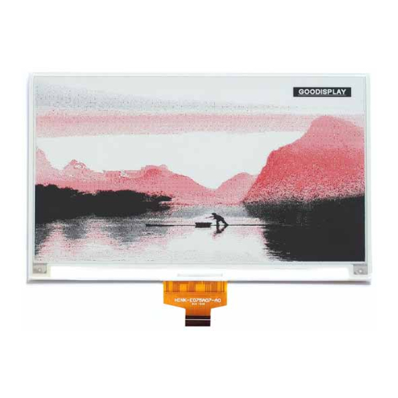
GDEH075Z90 1. General Description 1.1 Overview GDEH075Z90 is an Active Matrix Electrophoretic Display (AMEPD), with interface and a reference system design. The 7.5” active area contains528×880 pixels, and has 1- bit B/W/R full display capabilities. An integrated circuit contains gate buffer, source buffer, interface, timing control logic, oscillator, DC-DC. -
Page 6: Mechanical Drawing Of Epd Module
GDEH075Z90 1.4 Mechanical Drawing of EPD module www.good-display.com 6/38 7.5 inch Series... -
Page 7: Input/Output Terminals
GDEH075Z90 1.5 Input/Output Terminals Pin # Single Description Remark No connection and do not connect with other NC pins Keep Open N-Channel MOSFET Gate Drive Control RESE Current Sense Input for the Control Loop No connection and do not connect with other NC pins e Keep Open VSH2 Positive Source driving voltage... - Page 8 GDEH075Z90 Note 1.5-1: This pin (CS#) is the chip select input connecting to the MCU. The chip is enabled for MCU communication: only when CS# is pulled LOW. Note 1.5-2: This pin (D/C#) is Data/Command control pin connecting to the MCU. When the pin is pulled HIGH, the data will be interpreted as data.
-
Page 9: Reference Circuit
GDEH075Z90 1.6 Reference Circuit www.good-display.com 9/38 7.5 inch Series... -
Page 10: Matched Development Kit
GDEH075Z90 1.7 Matched Development Kit Our Development Kit designed for SPI E-paper Display aims to help users to learn how to use E-paper Display more easily. It can refresh black-white E- paper Display and three-color (black, white and red/Yellow) Good Display ‘s E- paper Display. -
Page 11: Environmental
GDEH075Z90 2. Environmental 2.1 HANDLING, SAFETY AND ENVIROMENTAL REQUIREMENTS WARNING The display module should be kept flat or fixed to a rigid, curved support with limited bending along the long axis. It should not be used for continual flexing and bending. Handle with care. Should the display break do not touch any material that leaks out. - Page 12 GDEH075Z90 Data sheet status Product specification The data sheet contains final product specifications. Limiting values Limiting values given are in accordance with the Absolute Maximum Rating System (IEC 134). Stress above one or more of the limiting values may cause permanent damage to the device. These are stress ratings only and operation of the device at these or any other conditions above those given in the Characteristics sections of the specification is not implied.
-
Page 13: Reliability Test
GDEH075Z90 Reliability test TEST CONDITION METHOD REMARK T=40℃ , RH=35%RH , For High-Temperature Operation IEC 60 068-2-2Bb 240Hr Low-Temperature Operation T = 0℃ for 240 hrs IEC 60 068-2-2Ab T=60℃ RH=35% RH For 240Hr High-Temperature Storage IEC 60 068-2-2Bb Test in white pattern T = -25℃... -
Page 14: Electrical Characteristics
GDEH075Z90 3. Electrical Characteristics 3.1 ABSOLUTE MAXIMUM RATING Table 3.1-1: Maximum Ratings Symbol Parameter Rating Unit Humidity Unit Note Logic supply voltage -0.5 to +6.0 Operation temperature range 0 to 40 °C 45 to70 Normal use is recommended to refresh every 24 hours Transportation temperature range -25 to 60 °C... -
Page 15: Serial Peripheral Interface Timing
GDEH075Z90 3.3 Serial Peripheral Interface Timing The following ℃ Write mode Symbol Parameter Min Typ Max Unit fSCL SCL frequency (Write Mode) tCSSU Time CSB has to be low before the first rising edge of SCLK tCSHLD Time CSB has to remain low after the last falling edge of SCLK tCSHIGH Time CSB has to remain high between two transfers tSCLHIGH Part of the clock period where SCL has to remain high tSCLLOW Part of the clock period where SCL has to remain low... -
Page 16: Mcu Interface
GDEH075Z90 3.5 MCU Interface 3.5.1MCU interface selection GDEH075Z90 can support 4-wire or 3-wire serial peripheral MCU interface, which is pin selectable by BS1 pin. The interface pin assignment for different MCU interfaces is shown in Table 3.5-1. Note L is connected to VSS H is connected to VDDIO Table 3.5-1: Interface pin assignment for different MCU interfaces... - Page 17 GDEH075Z90 Note: (1) L is connected to VSS and H is connected to VDDIO (2) ↑ stands for rising edge of signal (3) SDI is shifted into an 8-bit shift register on every rising edge of SCL in the order of D7, D6, ... D0. The level of D/C# should be kept over the whole byte. The data byte in the shift register is written to the Graphic Display Data RAM (RAM)/Data Byte register or command Byte register according to D/C# pin.
- Page 18 GDEH075Z90 3.5.3 MCU Serial Peripheral Interface (3-wire SPI) The 3-wire SPI consists of serial clock SCL, serial data input SDI, and CS#. The operation is similar to 4- wire SPI while D/C# pin is not used and it must be tied to LOW.
- Page 19 GDEH075Z90 In the read operation, serial data are transferred in the unit of 9 bits. After CS# pull low, the first byte is command byte, the D/C# bit is as 0 and following with the register byte. After command byte send, the following byte(s) are data byte(s), with D/C# bit is 1. After D/C# bit sending from MCU, an 8-bit data will be shifted out on every clock falling edge.
-
Page 20: Typical Operating Sequence
GDEH075Z90 4. Typical Operating Sequence 4.1 Normal Operation Flow www.good-display.com 7.5 inch Series 20/38... -
Page 21: Command Table
GDEH075Z90 5. COMMAND TABLE Command Table R/W# D/C# Command Description Driver Output control Gate setting A[9:0]= 2A7h [POR], 680 MUX MUX Gate lines setting as (A[9:0] + 1). B[2:0] = 000 [POR]. Gate scanning sequence and direction B[2]: GD Selects the 1st output Gate GD=0 [POR], G0 is the 1st gate output channel, gate output sequence is G0,G1, G2, G3, …... - Page 22 GDEH075Z90 Command Table R/W# D/C# Command Description Source Driving voltage Set Source driving voltage Control A[7:0] = 41h [POR], VSH1 at 15V B[7:0] = A8h [POR], VSH2 at 5V. C[7:0] = 32h [POR], VSL at -15V B[7] = 1, A[7]/B[7] = 0, C[7] = 0, VSH2 voltage setting from 2.4V to VSH1/VSH2 voltage setting from 9V...
- Page 23 GDEH075Z90 Command Table R/W# D/C# Command Description Deep Sleep Deep Sleep mode Control: mode A[1:0] : Description Normal Mode [POR] Enter Deep Sleep Mode 1 Enter Deep Sleep Mode 2 After this command initiated, the chip will enter Deep Sleep Mode, BUSY pad will keep output high.
- Page 24 GDEH075Z90 Command Table R/W# D/C# Command Description HV Ready Detection HV ready detection A[6:0] = 00h [POR] The command required CLKEN=1 and ANALOGEN=1. Refer to Register 0x22 for detail. After this command initiated, HV Ready detection starts. BUSY pad will output high during detection.
- Page 25 GDEH075Z90 Command Table R/W# D/C# Command Description Temperature Sensor Write Command to External temperature Control (Write sensor. Command to External A[7:0] = 00h [POR], temperature sensor) B[7:0] = 00h [POR], C[7:0] = 00h [POR], A[7:6] A[7:6] Select no of byte to be sent Address + pointer Address + pointer + 1st arameter Address + pointer + 1st...
- Page 26 GDEH075Z90 Enable Clock Signal, Then Load LUT with DISPLAY Mode 2 Enable Clock Signal, Then Load Temperature value from I2C Single Master Interface Then Load LUT with DISPLAY Mode 2 Enable Clock Signal, Then Load LUT with DISPLAY Mode 1 To Disable Clock Signal Enable Clock Signal, Then Load Temperature...
- Page 27 GDEH075Z90 Command Table R/W# D/C# Command Description Write RAM (BW) After this command, data entries will be written into the BW RAM until another command is written. Address pointers will advance accordingly For Write pixel: Content of Write RAM(BW) = 1 For Black pixel: Content of Write RAM(BW) = 0 Write RAM (RED)
- Page 28 GDEH075Z90 Command Table R/W# D/C# Command Description Write Register for This command is used to reduce glitch VCOM Control when ACVCOM toggle. Two data bytes D04h and D63h should be set for this command. Write VCOM register Write VCOM register from MCU interface A[7:0] = 00h [POR] A[7:0] VCOM...
- Page 29 GDEH075Z90 Command Table R/W# D/C# Command Description CRC calculation CRC calculation command for OTP content validation. BUSY pad will output high during operation. CRC Status Read CRC Status Read A[15:0] is the CRC readout Value Program Program OTP Selection according to the selection OTP Selection Control [R37h and R38h]...
- Page 30 GDEH075Z90 Command Table R/W# D/C# Command Description Reserved Reserved Reserved Reserved Border Waveform Select border waveform for VBD Control A[7:0] = C0h [POR], set VBD as HIZ. A [7:6] :Select VBD option A[7:6] Select VBD as GS Transition, Defined in A[1:0] Fix Level, Defined in A[5:4] VCOM...
- Page 31 GDEH075Z90 Command Table R/W# D/C# Command Description Specify the start/end positions of the address window address in the Y direction by an Start address unit for RAM position A[8:0]: YSA[8:0], YStart, POR = 000h B[8:0]: YEA[8:0], YEnd, POR = 2A7h Auto Write RED Auto Write RED RAM for Regular Pattern A[7:0] = 00h [POR]...
- Page 32 GDEH075Z90 Command Table R/W# D/C# Command Description Set RAM X Make initial settings for the RAM X address address in the address counter (AC) counter A[9:0]: 000h [POR]. Set RAM Y Make initial settings for the RAM Y address address in the address counter (AC) counter A[9:0]: 000h [POR].
-
Page 33: Optical Characteristics
GDEH075Z90 6. Optical characteristics 6.1 Specifications Measurements are made with that the illumination is under an angle of 45 degrees, the detection is perpendicular unless otherwise specified. T=25℃ SYMBOL PARAMETER CONDITIONS MIN TYP. UNIT Note Reflectance White Note 6.1-1 2Grey Level DS+(WS-DS)×n(m-1) Contrast Ratio Dark State L* value... -
Page 34: Definition Of Contrast Ratio
GDEH075Z90 6.2 Definition of contrast ratio The contrast ratio (CR) is the ratio between the reflectance in a full white area (R1) and the reflectance in a dark area (Rd)() : R1: white reflectance Rd: dark reflectance CR = R1/Rd 6.3 Reflection Ratio The reflection ratio is expressed as : R = Reflectance Factor white board x (L center / L white board ) -
Page 35: Point And Line Standard
GDEH075Z90 7. Point and line standard Shipment Inspection Standard Equipment:Electrical test fixture, Point gauge Outline 170.2(H)×111.2(V) Unit:㎜ Part-A Active area Part-B Border area dimension ×1.25(D) Temperature Humidity Illuminance Distance Time Angle Environment 55%±5%RH 35Sec 19℃~25℃ 800~1300Lux 300㎜ Standard Defet type Inspection method Part-A Part-B... - Page 36 GDEH075Z90 L=long W=wide D=point size www.good-display.com 7.5 inch Series 36/38...
-
Page 37: Packing
GDEH075Z90 8. Packing www.good-display.com 37/38 7.5 inch Series... -
Page 38: Precautions
GDEH075Z90 9. Precautions (1) Do not apply pressure to the EPD panel in order to prevent damaging it. (2) Do not connect or disconnect the interface connector while the EPD panel is in operation. (3) Do not touch IC bonding area. It may scratch TFT lead or damage IC function. (4) Please be mindful of moisture to avoid its penetration into the EPD panel, which may cause damage during operation.
Need help?
Do you have a question about the E-paper Series and is the answer not in the manual?
Questions and answers