Table of Contents
Advertisement
Quick Links
Operators Manual
Tool Control Interface (TCI) Multi
Manual - Issue 2
Crane Electronics Ltd.
NOTICE
ALL RIGHTS RESERVED. Reproduction of any part of this manual in any form whatsoever,
without the prior permission in writing from Crane Electronics Ltd is forbidden.
Copyright © March 2021 by Crane Electronics Ltd
1
Advertisement
Table of Contents

Summary of Contents for Crane Electronics TCI Multi
- Page 1 Manual - Issue 2 Crane Electronics Ltd. NOTICE ALL RIGHTS RESERVED. Reproduction of any part of this manual in any form whatsoever, without the prior permission in writing from Crane Electronics Ltd is forbidden. Copyright © March 2021 by Crane Electronics Ltd...
-
Page 2: Table Of Contents
CONTENTS Contents UKCA Marking, CE Marking & Compliance Product Disposal & About this Manual Packing List Care & Storage / Warnings Product Description Dimensions Specifications TCI Web Pages TCI Network Settings TCI Wrench Status TCI Log View TCI RF Settings TCI Jobs TCI Rounds TCI Global Settings... -
Page 3: Ukca Marking, Ce Marking & Compliance
Tel: +44 (0)1455 25 14 88 UKCA MARKING Crane Electronics Limited declares that the TCI Multi has been assessed and complies with the UK regulatory requirements. CE MARKING Crane Electronics Limited declares that the TCI Multi has been assessed and complies with the requirements of the relevant CE Directives. -
Page 4: Product Disposal & About This Manual
To enable this product to be disposed of properly i.e., cradle to grave, Crane Electronics is willing to accept the return of your product (at your cost) for recycling or alternatively, for more detailed information about recycling of this product please contact your local authority or the Distributor / Company where you have purchased the product. -
Page 5: Packing List
1 x Tool Control Interface 1 x User Manual 1 x Quick Start Guide 1 x 5V PSU Please ensure all items are present and notify Crane Electronics Ltd immediately of any shortages. CARE AND STORAGE Operating temperature range -20 to +50 degrees C... -
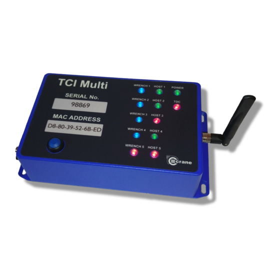
Page 6: Product Description
PRODUCT DESCRIPTION Status LED’s Mounting Hole (see Page 7 for dimensions) RF Antenna Blue Button Data capture for pairing Mini USB (programming only) Power Socket Reset RS232 RJ45 Ethernet... -
Page 7: Dimensions
DIMENSIONS Weight: 760g Construction: Aluminium housing containing printed circuit boards. Mounting Details... -
Page 8: Specifications
(TCI MULTI) SPECIFICATION Power: 5V +/-10% DC power supply 1000mA Ethernet: Unique MAC Address RJ45 Connection 10/100 MBit/s Serial: 9-way D-type RS232 socket for serial connection to a PC in standalone mode. USB: Mini USB Cable for programming firmware. 2400MHz antenna for RF Wrench communication that can be placed in different orientations. -
Page 9: Tci Web Pages
TCI WEB PAGES When you first login to the browser, you will see the Home Page. You can get back to the Home Page by clicking on the “Home” Icon at any time. There are 6 Web Pages that can be navigated to: TCI Network Settings •... - Page 10 The default password is “Admin” and we advise that you change this by clicking on the “Change password” Icon once logged in as Admin due to the password only remaining active for 5 minutes, after this time it will need to be re-entered to continue Editing. Once logged in, it is possible to perform a remote Factory Reset of the TCI as well as a change of language.
-
Page 11: Tci Network Settings
TCI NETWORK SETTINGS It shows the IP and Port address of the Web Pages. The unique MAC address of the TCI is shown. This cannot be changed. This is useful if the IT system needs to check a valid device is connected to a certain network node. If the user is logged in then the Web Page will show a “Change Network Settings”... -
Page 12: Tci Wrench Status
The Edit entry warns you if the number entered is incorrect. IP address entry is from 0 to 255 Port entry is from 0 to 65353 TCI WRENCH STATUS It shows the Status for up to 5 connected Wrenches. Note: Info on Port 80 can be viewed at the same time as the measurement results are being transmitted to Port 4545. - Page 13 Will be “Connected” if a Start Comm MID was received and it continued to receive messages or a Keep Alive MID message. The Torque and Angle result for the last reading will be displayed and colour coded the same as the •...
- Page 14 Change Transducer Settings – Retry Settings This setting controls what happens when there is a NOK reading and when a retry should be triggered. Never – Accepts any reading on the wrench and does not trigger retry. Manual – Screen prompt when NOK giving the user the opportunity to save the reading and cancel the retry. Always –...
- Page 15 Change Transducer Settings – Vibrator Settings This setting enables/disables the vibrator. Change Transducer Settings – Mode of Operation There are two settings available, production and Audit. Audit gives the user more time to read the result on the wrench after each reading and will zero the wrench before every new reading is taken. Production jumps straight to the next job after a reading and only zeros the wrench when it is first turned on.
- Page 16 Enabled This setting enables the light ring during the cycle. The light ring will light amber for a low reading, green for an OK reading and Red for a high reading. This setting also enables the 3-vibration points spread out through the cycle. See the “Set vibrator activation point”...
- Page 17 Double Hit Detect This feature only works when pulling Torque in the clockwise direction. When the angle with the cycle is less than the specified angle when this setting is enabled, there will be a NOK triggered for double hit. When enabled with Rehit result store is selected the results for the NOK will be saved when it occurs.
- Page 18 Set Vibrator Activation Point Controls the point at which the vibrator kicks in within a cycle when the indication while pulling setting is set to ‘Enabled’. There will be 3 vibrations that happen at different times in the cycle. This helps the user understand where in the cycle they are at a given time.
- Page 19 Change Power Off Time This setting sets the Auto Power of time on the wrench. This is highly recommended if the wrench isn’t docked in the cradle between jobs and if multiple wrenches are being used with 1 TCI. The more wrenches on and paired to the TCI, the greater the RF interference in that area.
-
Page 20: Tci Log View
TCI Log View Page TCI LOG VIEW The TCI can log message information to help diagnose problems. The TCI has the option of viewing either host messages, or WrenchStar Multi messages, or both. The logging options are setup via TCI Exchange. The log information will appear in the “Log Box”... - Page 21 The TCI base address should be set between 1 and 65353. Each TCI should be given a unique base address so that WrenchStar Multi’s Paired with a particular TCI will only communicate with that TCI and no other. The RF power typically gives the following ranges: 0 = 1m 1 = 4m 2 = 9m...
-
Page 22: Tci Jobs
TCI JOBS TCI Jobs Page The TCI can store up to 256 Jobs. The load a job on wrench feature on this page only works in “Website Manual Mode” and “Auto Print Mode” as setup in the global settings. There are two options to load Jobs on TCI, Open Protocol or via the Web Page shown above. By clicking the Edit Button on a particular Job, it is possible to Edit its parameters. -
Page 23: Tci Rounds
TCI ROUNDS It is possible to set up to 5 jobs into a single sequence of jobs. The WSM will auto proceed to next job on completion. the Job must have a batch size greater than zero. Jobs Export This feature is used to export these jobs to a CSV file as backup to be uploaded later. Jobs Import This feature allows for the import of jobs backup onto the TCI. -
Page 24: Tci Global Settings
TCI GLOBAL SETTINGS All global settings are read only is when a user is not logged. After logging in all settings can be accessed by the user. Login Timeout Setting this to a value between 1 and 60 sets the time in minutes before the TCI will automatically log out. Setting this to 0 will disable the automatic log out. - Page 25 Backup Reading Storage Enabling this will result in TCI storing backup of each reading in FIFO, allowing them to be printed via serial port whenever requested. The Crane Reading Capture Software can be used to retrieve this data. RS232 Baud Rate Changes the baud rate of the RS232 port.
- Page 26 Wrench Span Pairing If value for given port is not 0, when pairing with blue button TCI will try to pair to a specific port based on span of the Wrench. If all spans are set to 0 then the blue button on the front of the TCI will always pair the wrench to the first port.
- Page 27 TDC – This is no longer used Open Protocol Mode...
- Page 28 Automatic Tool Enable in Open Protocol This setting will force TCI to automatically enable tool when previous result has been acknowledged. This should be disabled in systems, which prefer to send Enable Tool after each result. Open Protocol Variant This setting controls which variant of Open Protocol should be used as different plants use the Open Protocol standard in slightly different ways.
- Page 29 Traces in Open Protocol Enabling this will allow Traces to be stored inside WSM and then transferred over the RF after each tightening. Traces will be sent over the Open Protocol using MID0900 and MID0901, assuming trace subscription is enabled. User needs to make sure that Wrench Global Setting for Trace Length is set accordingly. Minimum Trace Integrity This setting controls minimum % of sample the TCI will except when attempting to fetch the Trace from the wrench via RF.
- Page 30 Lock Tool on Batch Complete Used together with MID0410/0411 and MID0019. If setting is disabled, then TCI will continue even though batch count had been reached and readings were OK. Logs keep alive messages If disabled, any keep alive messages MID9999 will not be logged in the log file. This dramatically extends the life of the log file.
- Page 31 AutoPrint Mode Auto print allows printing of a string to the RS232 port of the TCI. By changing the AutoPrint options shown below, information can be added/removed from the output string. PokeYoke...
- Page 32 These settings are to be used when connected to a PokeYoke system and controls which wrench is selected and how many jobs are queued. Automatic Tool Enable in PokeYoke Mode This setting will force TCI to automatically enable tool after result has been sent to PokeYoke. Quality Data ACK need not be sent to re-enable measurements after each reading.
Need help?
Do you have a question about the TCI Multi and is the answer not in the manual?
Questions and answers