Table of Contents
Advertisement
Advertisement
Table of Contents

Summary of Contents for ISON IS-MS3180 Series
- Page 1 IS-MS3180 Series User Manual Tiny Modbus/TCP to RTU/ASCII Gateway...
-
Page 2: Table Of Contents
Serial COM Ports ......................- 12 - DIN-Rail Mounting ..................... - 12 - Dimensions ....................- 13 - IS-MS3180 Series Module ..................- 13 - CA-002 Cable ......................- 14 - Pin Assignments ..................- 15 - IS-MS3180 ........................- 15 - Wiring Notes for RS-232/485/422 Interfaces ........... - Page 3 4.3.3 Modbus Settings ..................- 32 - 4.3.4 Restore Factory Defaults ................- 34 - Serial Port Page................... - 36 - 4.4.1 Settings (Port1 Settings) ................- 36 - 4.4.2 Settings (Pair-Connection Settings) ............- 39 - Filter Page ....................- 40 - Monitor Page ....................
-
Page 4: Introduction
1. Introduction Modbus has become the standard protocol for industrial communication and is now the most commonly available means of connecting industrial electronic devices. Modbus allows for communication between many devices connected to the same RS-485 network, for example, a system that measures temperature and humidity and communicates the results to a computer. - Page 5 In harsh industrial environments, the IS-MS3180 series also adds 3000 V and +/- 4 kV ESD protection component that diverts the potentially damaging charge away from sensitive circuit to protects the module and equipment from the sudden and momentary electric current.
-
Page 6: Features
1.1 Features Supports Modbus TCP/UDP master and slave Supports Modbus RTU/ASCII master and slave Max. connections (masters) per serial port: 32 Read-cache ensures faster Modbus TCP/UDP response Supports UDP responder for device discovery (UDP Search) ... -
Page 7: Applications
1.2 Applications Factory Automation Building Automation Home Automation Remote Diagnosis and Management 1.3 Ethernet Solutions Nowadays, the Ethernet protocol has become the foremost standard for local area networks. Connectivity via the Internet snow common in many of the latest applications from home appliances, to vending machines, to testing equipment, to UPS, etc. -
Page 8: Web Server Technology
1.4 Web Server Technology Web server technology enables the IS-MS3180 to be configured via a standard web browser interface, e.g., Google Chrome, Internet Explorer, or Firefox, etc. This means that it is easy to check the configuration of the IS-MS3180 via an Ethernet network without needing to install any other software tools, thereby reducing the learning curve required for maintaining the device. -
Page 9: Hardware Information
2. Hardware Information This chapter provides a detailed description of the front panel, the hardware specifications, the pin assignments, the wiring notes and the dimensions for the IS-MS3180 series modules. 2.1 Specifications Model IS-MS3180 System 32-bit ARM Communication Interface 10/100 Base-TX, 8-pin RJ-45 x 1, (Auto-negotiating, Auto-MDI/MDIX, LED indicator) Ethernet PoE (IEEE 802.3af, Class 1) -
Page 10: Appearance
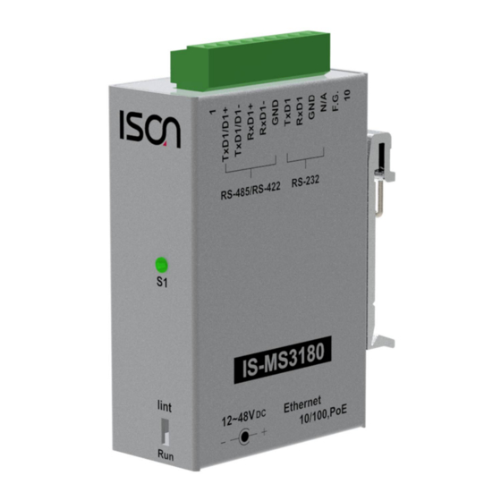
2.2 Appearance 5. Serial COM Ports 4. LED indicator 6. DIN-Rail Mounting 1. PoE and Ethernet 3. Operating Mode RJ-45 Jack Switch 2. +12 to +48 V Jack PoE and Ethernet RJ-45 Jack The IS-MS3180 module is equipped with an RJ-45 jack that is used as the 10/100 Base-TX Ethernet port and features networking capabilities. -
Page 11: Operating Mode Switch
Run Mode: Firmware operation Init Mode: Configuration mode For IS-MS3180 series modules, the operating mode switch is set to the Run position by default. In order to update the firmware for the IS-MS3180 series module, the switch must be moved from the Run position to the Init position. -
Page 12: Serial Com Ports
Assignments. DIN-Rail Mounting The IS-MS3180 series modules include simple rail clips on the bottom of the chassis that allow them to be reliably mounted on a DIN-Rail or a wall. For more detailed information regarding DIN- Rail Mounting, refer to the illustration in figure below. -
Page 13: Dimensions
2.3 Dimensions The following diagrams provide the dimensions of the IS-MS3180 series module and CA-002 cable that can be used as a reference when defining the specifications and the DC power supply plug for any custom enclosures. All dimensions are in millimeters. -
Page 14: Ca-002 Cable
CA-002 Cable Note: Cable color: BLACK Pin Assignment DESCRIPTION UNIT UL2464 18AWG 2C(RED/BLACK) OPEN 0D5.0 COLOR BLACK BLACK OPEN DC PLUG 5.5*2.1 PVC:45/P BLACK - 14 -... -
Page 15: Pin Assignments
2.4 Pin Assignments IS-MS3180 Terminal No. Pin Assignment F.G. ISO.GND RS-232 RxD1 TxD1 ISO.GND RxD1- RS-485/RS-422 RxD1+ TxD1-/D1- TxD1/D1+ - 15 -... -
Page 16: Wiring Notes For Rs-232/485/422 Interfaces
2.5 Wiring Notes for RS-232/485/422 Interfaces RS-232 Wiring 3-wire RS-232 Connection RS-422 Wiring - 16 -... -
Page 17: Rs-485 Wiring
RS-485 Wiring Notes: 1. Usually, you have to connect all signal grounds of RS-422/485 devices together to reduce common-mode voltage between devices. 2. Twisted-pair cable must be used for the DATA+/- wires. 3. Both two ends of the cable may require a termination resistor connected across the two wires (DATA+ and DATA-). -
Page 18: Getting Started
This chapter provides detailed information about the “Self-Test” process, which is used to confirm that the IS-MS3180 series module is operating correctly. Before beginning the “Self-Test” process, the wiring test, Ethernet configuration and search/Modbus utility driver installation procedures must first be fully completed. -
Page 19: Configuring Network Settings
3.2 Configuring Network Settings 1. Install the ISON eSearch Utility according to the installation instructions. The ISON eSearch Utility can be obtained from the companion CD-ROM 2. Double click the ISON eSearch Utility shortcut on the desktop. 3. Click the “Search Servers” button to search your IS-MS3180. - Page 20 5. Enter the network settings information, including the IP, Mask and Gateway addresses, and then click “OK” button. The new settings for the IS-MS3180 will take effect within 2 seconds. If you don’t know the correct network configuration information, contact your Network Administrator to obtain the details.
-
Page 21: Connecting The Modbus Devices
1. Open a web browser, such as Google Chrome, Internet Explorer, or Firefox, and enter the URL for the IS-MS3180 module in the address bar of the browser or click the “Web” button in the ISON eSearch Utility. 2. When the login screen is displayed, enter the password (use the default password: admin) in the login password field, and then click the “Submit”... - Page 22 3. Click the “Port1” tab to display the Port1 Settings page. 4. Select the appropriate Baud Rate, Data Format and Modbus Protocol (e.g., 19200, 8N2 and Modbus RTU) from the relevant drop-down options. Notes: 1. The Baud Rate, Data Format and Modbus protocol settings depends on your Modbus device. 2.
-
Page 23: Self-Test
3.5 Self-Test 1. In the ISON eSearch Utility, select the “Modbus TCP Master” item from the “Tools” menu to open the Modbus TCP Master Utility. 2. In the Modbus TCP Master Utility, enter the IP address of IS-MS3180 in the “Modbus TCP”... -
Page 24: Web Configuration
ISON eSearch Utility described above, or via a standard web browser. 4.1 Logging in to the IS-MS3180 Web Server The embedded IS-MS3180 series web server can be accessed from any computer that has an Internet connection. Step 1: Open a new browser window Open a web browser, for example, Google Chrome, Firefox or Internet Explorer, which are reliable and popular Internet browsers that can be used to configure IS-MS3180 series module. - Page 25 Step 3: Enter the Password After the main login page is displayed, enter a password (the factory default password is “admin”), and then click the “Submit” button to continue. Use the default password: admin Step 4: Log in to the IS-MS3180 Web Server After logging into the IS-MS3180 web server, the main page will be displayed.
-
Page 26: Home Page
4.2 Home Page The Home link connects to the main page, which contains two parts. The first part of this page provides basic information about the IS-MS3180 hardware and software. The software and hardware information section include information related to the Model Name, the current Firmware version, the IP Address, the current position of the Initial Switch, the Alias, the MAC Address, and the TCP Port, and the System Timeout values. - Page 27 The lower section provides information related to the port settings and pair-connection settings. - 27 -...
-
Page 28: Network Page
4.3 Network Page After clicking the Network tab, the Network page will be displayed, allowing you to verify the current settings, configure the IP Address, and the general parameters, and restore the default settings for the IS-MS3180 module, each of which will be described in more detail below. 4.3.1 IP Address Selection The Address Type, Static IP Address, Subnet Mask and Default Gateway values are the most important network settings and should always correspond to the LAN configuration. - Page 29 The following is an overview of the parameters contained in the IP Address Selection section: Item Description Static IP: If no DHCP server is installed on the network, the network settings can be configured manually. Refer to Section “Manual Configuration” for more details.
- Page 30 Manual Configuration When using manual configuration, the network settings should be assigned in the following manner: Step 1: Select the “Static IP” option from the “Address Type” drop-down menu. Step 2: Enter the relevant details in the respective network settings fields. Step 3: Click the “Update Settings”...
-
Page 31: General Settings
(192.168.0.1:81). This parameter is used to assign an alias for each IS-MS3180 to assist with Alias Name ISON easy identification. This parameter is used to configure the system timeout value. If there is no activity on the network for a specific period of time, the system will be rebooted System Timeout based on the configured system timeout value. -
Page 32: Modbus Settings
4.3.3 Modbus Settings The following is an overview of the parameters contained in the Modbus Settings section: Item Description Default Gateway Net ID This is reserved for gateway. (Not used to set the slave device) This parameter is used to enable or disable whether the slave response is checked for compatibility with the Modbus RTU format. - Page 33 This parameter is used to enable or disable whether a slave/data timeout exception error is reported by the Gateway. If There is no response from a slave device, a 0x0B exception error will be reported. If serial data is being Timeout Exception received, a 0x4B exception will be reported.
-
Page 34: Restore Factory Defaults
Step 2: Click the “OK” button in the message dialog box. Step 3: Check whether the module has been reset to the original factory default settings for use with the ISON eSearch Utility. Refer to Chapter for more details. ... - Page 35 The Forced Reboot function: can be used to force the IS-MS3180 to reboot or to remotely reboot the device. After the IS-MS3180 module has rebooted, the original login screen will be displayed requesting that you enter your Login Password before continuing. ...
-
Page 36: Serial Port Page
4.4 Serial Port Page After clicking the Port1 tab, the serial port settings page will be displayed, allowing you to configure the settings for the IS-MS3180, including the Baud Rate, Data Format, Slave Timeout, Char Timeout, Silent Time, Read Cache, TCP Timeout, Modbus Protocol and Pair-connection parameters, etc., each of which will be described in more detail below. - Page 37 Item Description Default Port Settings Baud Rate (bps) This parameter is used to set the Baud Rate for the COM ports. 115200 Data Size (bits) This parameter is used to set the Data Size for the COM ports. Parity This parameter is used to set the Parity for the COM ports. None Stop Bits (bits) This parameter is used to set the Stop Bits for the COM ports.
- Page 38 Item Description Default Modbus RTU requires 3.5 char time between messages. This parameter is used to set the waiting time (based on bytes) that should elapse after last byte of data of the response is received from the slave device is activated. If no more data is received before the Char Timeout (bytes) timeout period expires, then the transmission of this packet is deemed to have been completed and the IS-MS3180 begins...
-
Page 39: Settings (Pair-Connection Settings)
4.4.2 Settings (Pair-Connection Settings) The following is an overview of the parameters contained in the Settings – Pair-Connection Settings (Master/Slave Mode) section: Item Description Pair-Connection Settings (Master/Slave Mode) Application Mode Server (default) Client Select the Modbus protocol (Modbus TCP or UDP) for Network Protocol the remote device Remote Server IP... -
Page 40: Filter Page
4.5 Filter Page The Accessible IP (filter is disabled when all zero) Settings page is used to query or edit the IP Filter List. The IP Filter List restricts the access of packets based on the IP header. If one or more IP address are saved to the IP Filter table, only clients whose IP is specified in the IP Filter List can access the IS-MS3180. -
Page 41: Monitor Page
4.6 Monitor Page After clicking the Monitor tab, the Current Connection Status page will be displayed showing detailed information regarding the current status of the serial port connection settings for the IS- MS3180. - 41 -... -
Page 42: Password Page
4.7 Password Page After clicking the Password tab, the Change Password page will be displayed. To change a password, first enter the old password in the “Current password” field (use the default password “admin”) and then enter a new password in the “New password” field. Re-enter the new password in the “Confirm new password”... -
Page 43: Logout Page
4.8 Logout Page After clicking the Logout tab, you will be immediately logged out from the system and be returned to the login page. - 43 -... -
Page 44: Typical Applications
5.2 Modbus Net ID The IS-MS3180 series module is a gateway that can be used to convert between the Modbus TCP/UDP protocol and the Modbus RTU/ASCII protocol. Consequently, SCADA/HMI applications is able to access each Modbus RTU/ASCII slave device via the IS-MS3180 gateway by specifying correct NetID of the intended slave device in each Modbus TCP request. -
Page 45: Pair-Connection Applications
MS3180#2 can be different. Step 1: Connecting to a network, PC and Power 1. Confirm that the IS-MS3180 modules are functioning correctly. For detailed information regarding how to install, configure and operate your IS-MS3180 series module, refer to Chapter 3 “Getting Started”. - Page 46 Step 3: Configuring the Pair-connection (Client Mode) on the Web Server for IS-MS3180#1 1. Open the ISON eSearch Utility to search for the IS-MS3180 modules connected to the network. Click the name of the first tGW-715 module (IS-MS3180#1) to select it, and then click the “Web”...
- Page 47 Server for IS-MS3180#2 1. In the ISON eSearch Utility, click the name of the second IS-MS3180 #2 to select it, and then click the “Web” button to launch a browser window to connect to the web server on the IS-MS3180 #2 module.
- Page 48 - 48 -...
-
Page 49: Tcp Client Mode Applications
Step 1: Connecting to a network, a PC and a Power Supply 1. Confirm that the IS-MS3180 device is functioning correctly. For detailed information regarding how to install, configure and operate your IS-MS3180 series module, refer to Chapter 3 “Getting Started”. - Page 50 Step 3: Configuring Pair-connection (TCP Client Mode) on the Web Server for the IS-MS3180 module 1. Open the ISON eSearch Utility to search for the IS-MS3180 modules connected to the network. Click the name of the first IS-MS3180 module to select it, and then click the “Web” button to launch a browser window to connect to the web server on the IS-MS3180 module.
-
Page 51: Modbus Information
6. Modbus Information What is Modbus TCP/IP? Modbus is a communication protocol developed by Modicon in 1979. You can also visit http://www.modbus.org to find more valuable information. The Different versions of Modbus used today include Modbus RTU (based on serial communication interfaces such as RS485 and RS232), Modbus ASCII and Modbus TCP, which is the Modbus RTU protocol embedded into TCP packets. - Page 52 Leading 6 bytes of Modbus/TCP protocol: Byte 00 Byte 01 Byte 02 Byte 03 Byte 04 Byte 05 Length field Length field Transaction identifier Protocol identifier (upper byte ) (lower byte) Transaction identifier: Assigned by Modbus/TCP master (client) Protocol identifier: 0 Length field (upper byte): 0 (since all messages are smaller than 256) Length field (lower byte): Number of following RTU data bytes RTU Data Structure...
- Page 53 Code Function Reference (Address) 01 (0x01) Read the Status of the Coils (Readback DOs) 0xxxx 02 (0x02) Read the Status of the Input(Reads DIs) 1xxxx 03 (0x03) Read the Holding Registers (Readback AOs) 4xxxx 04 (0x04) Read the Input Registers (Reads AIs) 3xxxx 05 (0x05) Force a Single Coil (Writes DO)
-
Page 54: 0X01) Read The Status Of The Coils (Readback Dos)
01(0x01) Read the Status of the Coils (Readback DOs) This function code is used to read either the current status of the coils or the current digital output readback value. [Request] Byte Description Size Value Net ID (Station Number) 1 Byte 1 to 247 Function Code 1 Byte 0x01 Refer to the Modbus address depends on your slave device for more details. -
Page 55: 0X02) Read The Status Of The Input (Read Dis)
02(0x02) Read the Status of the Input (Read DIs) This function code is used to read the current digital input value. [Request] Byte Description Size Value Net ID (Station Number) 1 Byte 1 to 247 Function Code 1 Byte 0x02 Refer to the Modbus address depends on your slave device for more details. -
Page 56: 0X03) Read The Holding Registers (Readback Aos)
03(0x03) Read the Holding Registers (Readback AOs) This function code is used to readback either the current values in the holding registers or the analog output value. [Request] Byte Description Size Value Net ID (Station Number) 1 Byte 1 to 247 Function Code 1 Byte 0x03 Refer to the Modbus address depends on your slave device for more details. -
Page 57: 0X04) Read The Input Registers (Read Ais)
04(0x04) Read the Input Registers (Read AIs) This function code is used to read either the input registers or the current analog input value. [Request] Byte Description Size Value Net ID (Station Number) 1 Byte 1 to 247 Function Code 1 Byte 0x04 Refer to the Modbus address depends on your slave device for more details. -
Page 58: 0X05) Force A Single Coil (Write Do)
05(0x05) Force a Single Coil (Write DO) This function code is used to set the status of a single coil or a single digital output value. [Request] Byte Description Size Value Net ID (Station Number) 1 Byte 1 to 247 Function Code 1 Byte 0x05 Refer to the Modbus address depends on your slave device for more details. -
Page 59: 0X06) Preset A Single Register (Write Ao)
06(0x06) Preset a Single Register (Write AO) This function code is used to set a specific holding register to store the configuration values. [Request] Byte Description Size Value Net ID (Station Number) 1 Byte 1 to 247 Function Code 1 Byte 0x06 Refer to the Modbus address depends on your slave device for more details. -
Page 60: 0X0F) Force Multiple Coils (Write Dos)
15(0x0F) Force Multiple Coils (Write DOs) This function code is used to set multiple coils status or write multiple digital output values. [Request] Byte Description Size Value Net ID (Station Number) 1 Byte 1 to 247 Function Code 1 Byte 0x0F Refer to the Modbus address depends on your slave device for more details. -
Page 61: 0X10) Preset Multiple Registers (Write Aos)
16(0x10) Preset Multiple Registers (Write AOs) This function code is used to set multiple holding registers that are used to store the configuration values. [Request] Byte Description Size Value Net ID (Station Number) 1 Byte 1 to 247 Function Code 1 Byte 0x10 Refer to the Modbus address depends on your slave device for more details. -
Page 62: Appendix A: Troubleshooting
"Init" position. Reboot the module to load factory default settings including default web password. Step 2 Execute either the ISON eSearch Utility to search for any IS-MS3180 modules connected to the network. Verify that the IS-MS3180 has been reset to the original factory default settings. For example, the module should be shown as having the default IP address, which is 192.168.0.1. - Page 63 Step 3 Double-click the name of the module to open the Configure Server (UDP) dialog box, and modify the basic settings as necessary, e.g., the IP, Mask and Gateway addresses, and then click the "OK" button to save the new settings. Step 4 Reset the Init/Run switch on the IS-MS3180 module to the "Run"...
-
Page 64: Appendix B: Actual Baud Rate Measurement
Appendix B: Actual Baud Rate Measurement Ideal Baud Rate (bps) Actual Baud Rate (bps) Error 0.00% 109.92 0.07% 298.48 0.51% 597.04 0.49% 1200 1197.6 0.20% 2400 2395.2 0.20% 4800 4790.4 0.20% 9600 9568.0 0.33% 14400 14392 0.05% 19200 19136 0.33% 38400 38464 0.17% 57600 57552 0.08% 115200... -
Page 65: Appendix C: Exception Codes
Appendix C: Exception Codes If an exception occurs during Modbus communication, the slave device will return an Exception Code in the response message. The following is an explanation of the Exception Codes: Exception Codes: Code Name and Description ILLEGALFUNCTION Indicates that the function code received in the query is not an allowable action for the slave. If not an 0x01 allowable action for the slave. - Page 66 Defined Exception Codes for IS-MS3180: Code Name and Description GATEWAYTARGETDEVICEFAILEDTORESPOND 0x0B Timeout. The slave device does not respond within the timeout value, the IS-MS3180 will return this code. GATEWAYTARGETDATAFAILEDTORESPOND 0x4B Timeout. The slave device is still sending data when timed out, the IS-MS3180 will return this code. Please use larger Slave Timeout value for the serial port of the IS-MS3180 module.
Need help?
Do you have a question about the IS-MS3180 Series and is the answer not in the manual?
Questions and answers