Advertisement
Quick Links
ONE STOP MONITORING SOLUTIONS | HYDROLOGY | GEOTECHNICAL | STRUCTURAL | GEODETIC
Over 50 years of excellence through ingenuity
USERS' MANUAL
WIRELESS ANALOG NODE
MODEL EWN-01A/04A
Doc. # WI 6002.131 R00 | May 2020
ENCARDIO-RITE ELECTRONICS PVT. LTD.
A-7, Industrial Estate, Talkatora Road Lucknow, UP - 226011, India | P: +91 522 2661039-42 | Email: geotech@encardio.com | www.encardio.com
International: UAE | Qatar | Bahrain | Bhutan | Europe | UK | USA
India: Lucknow | Delhi | Kolkata | Mumbai | Chennai | Bangalore | Hyderabad | J&K
Advertisement

Related Manuals for ENCARDIO RITE EWN-01A

Summary of Contents for ENCARDIO RITE EWN-01A
- Page 1 Over 50 years of excellence through ingenuity USERS’ MANUAL WIRELESS ANALOG NODE MODEL EWN-01A/04A Doc. # WI 6002.131 R00 | May 2020 ENCARDIO-RITE ELECTRONICS PVT. LTD. A-7, Industrial Estate, Talkatora Road Lucknow, UP - 226011, India | P: +91 522 2661039-42 | Email: geotech@encardio.com | www.encardio.com International: UAE | Qatar | Bahrain | Bhutan | Europe | UK | USA India: Lucknow | Delhi | Kolkata | Mumbai | Chennai | Bangalore | Hyderabad | J&K...
-
Page 2: Table Of Contents
Users’ Manual Analog Node Contents QUICK START GUIDE SETTING UP WIRELESS ANALOG NODE Installation Node Setup Configuring via the ER Beam Offline App www.encardio.com... -
Page 3: Quick Start Guide
Users’ Manual Analog Node QUICK START GUIDE Generally, we send devices pre-configured. If your devices are pre-configured by us, please go through the user-friendly procedure to get started with your ER Beam system, which takes only a few minutes to get the process rolling. -
Page 4: Setting Up Wireless Analog Node
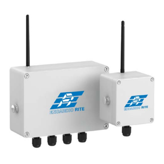
Users’ Manual Analog Node SETTING UP WIRELESS ANALOG NODE This section provides information on setting up an Analog Node to work with the offline ER Beam gateway. Installation The Nodes can be directly affixed to a flat surface using M6 screws. However, for more sophisticated mounting scenarios, we recommend using the node bracket. -
Page 5: Node Setup
Users’ Manual Analog Node Node Setup Connect the node antenna to the antenna bulkhead. Connect the sensor wires to the node while ensuring that the wires are plugged in correctly. Voltage Output Sensors PWR: +Voltage input to sensor (e.g. +12V) GND: 0 Voltage input to sensor (e.g. -
Page 6: Configuring Via The Er Beam Offline App
Users’ Manual Analog Node -T: Thermistor SHLD: Shield wire of sensor Switch off the Node and insert the battery while ensuring the correct polarity. Configuring via the ER Beam Offline App Obtain an Android phone and connect it to the ER_Beam Wi-Fi network. (See the Gateway section to learn about switching on the ER_Beam Wi-Fi network.) Connect the Android smartphone to the Node via an OTG adapter. - Page 7 Users’ Manual Analog Node Search for the project, which you have already created once you open your ER app. Select and click the button to download the project and enter in to the project, where the project details would be mentioned. Page | 5...
- Page 8 Users’ Manual Analog Node (ii) Click on “Setup Device” on the menu (at the bottom of screen), the app will show connected node information. (iii) Optional Step: If Wireless Mesh (Relay) function is to be deployed, click on "Wireless Mesh" toggle button to enable.
- Page 9 Users’ Manual Analog Node After clicking ‘Setup Sensor’, sensor setup page will open with the available channels Tap the “Arrow icon” on the respective channel which your sensor is connected to. (vi) Sensor setting can be made as follows: Sensor Code: Desired sensor name.
- Page 10 Users’ Manual Analog Node (vii) Click Save Settings. The Node will now read the configured sensor. (viii) On next page, you will see the first reading. (ix) To get another reading, click on the arrow icon. If the reading is ok, enable the sensor by switching on the android icon (colour changing to blue).
- Page 11 Users’ Manual Analog Node Repeat above steps to configure other sensors connected to the Node. (xi) Once all sensors are configured, click on “Enable Sensor” button. It will take you to next page “Scanning Network” which will scan the wireless signal strength (RSSI) between the Node and Gateway.
- Page 12 Users’ Manual Analog Node (xiii) Next, click “Start Monitoring” button then the app will prompt, “Device commissioned”. Click OK. (xiv) Press the Project Sync button at lower right area to send all the configuration information back to the gateway. Page | 10...
- Page 13 Users’ Manual Analog Node (xv) If you would like to get the Node to immediately send a reading to the Gateway, press the “SYS TEST” button on the device’s printed circuit board as shown below. (xvi) For commissioning of additional Nodes, repeat the above steps. (xvii) Now proceed to the Gateway software dashboard on your Laptop and click on your project.
Need help?
Do you have a question about the EWN-01A and is the answer not in the manual?
Questions and answers