Table of Contents
Advertisement
Available languages
Available languages
DETECTION DE CHOCS SUR CLOTURE
FR
Notice d'installation -
FENCE SHOCK DETECTION SYSTEM
EN
Installation manual -
1, rue du Dauphiné – 69120 – VAULX-EN-VELIN – FRANCE
Tél. : +33(0)4.78.03.06.10 - Fax : +33(0)4.78.68.24.61
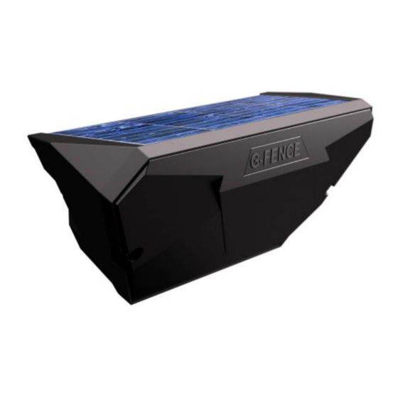
G-FENCE
Pages 1-24
Pages 25-48
Site web :
www.sorhea.com
Email :
commercial@sorhea.fr
NT293 / V2.3 / 01.15
Advertisement
Chapters
Table of Contents

Related Manuals for SORHEA G-FENCE

Summary of Contents for SORHEA G-FENCE
- Page 1 G-FENCE DETECTION DE CHOCS SUR CLOTURE Notice d’installation - Pages 1-24 FENCE SHOCK DETECTION SYSTEM Installation manual - Pages 25-48 1, rue du Dauphiné – 69120 – VAULX-EN-VELIN – FRANCE Tél. : +33(0)4.78.03.06.10 - Fax : +33(0)4.78.68.24.61 Site web : www.sorhea.com...
-
Page 2: Table Of Contents
SORHEA G-FENCE SOMMAIRE GENERALITES ...................... 2 DESCRIPTION DU SYSTEME ................3 Principe ..........................3 Câble détecteur ........................3 Unité de Gestion (UG) ......................3 Unité de Terminaison / Raccordement (UT/UR) ..............3 INSTALLATION ..................... 4 Installation de l’Unité de Gestion (UG) .................. 4 Installation du câble détecteur .................... -
Page 3: Generalites
SORHEA G-FENCE GENERALITES Le système G-Fence détecte toutes les tentatives d’intrusion par coupure, escalade ou arrachement de la clôture sur laquelle il est installé en filtrant les phénomènes météorologiques tels que le vent, la pluie ou les vibrations parasites (véhicule...) G-FENCE est composé... -
Page 4: Description Du Systeme
SORHEA G-FENCE DESCRIPTION DU SYSTEME 2.1 Principe Portail 100 m 70 m 30 m 100 m Câble non détecteur 100 m 100 m 100 m 100 m 100 m 2.2 Câble détecteur Le câble détecteur intègre 40 capteurs espacés de 3m à installer sur la clôture. -
Page 5: Installation
SORHEA G-FENCE INSTALLATION 3.1 Installation de l’Unité de Gestion (UG) Ne pas installer d’Unité de Gestion (UG) devant une haie ou une zone ombragée pour ne pas masquer le panneau solaire Installer l’Unité de Gestion (UG) en haut de la clôture. -
Page 6: Installation Du Câble Détecteur
SORHEA G-FENCE 2. Installer l’Unité de Gestion (UG) à une hauteur comprise entre 1m50 et 1m80. Serrer un des crochets sur le croisement d’une maille de la clôture et l’autre sur le fil horizontal. Crochet serré sur le croisement d’une maille de la clôture... -
Page 7: Installation Des Unités De Terminaison / Raccordement (Ut/Ur)
SORHEA G-FENCE Nota : Installer 2 capteurs sur chaque panneau où sont installées les Unités de Gestion Unité de Gestion Capteur 1 Capteur 1 câble détecteur câble détecteur 2 2. Fixer le câble le long de la clôture à l’aide des serre-câbles fournis. -
Page 8: Raccordement
SORHEA G-FENCE RACCORDEMENT 4.1 Raccordement à l’Unité de Gestion (UG) 1 2 3 4 5 6 7 8 9 10 11 12 13 14 15 16 Raccordement d’usine Alim Externe (*) Entrées auxiliaire : Liaison RS485 avec MAXIBUS III : 5 - Entrée de l’auxiliaire 1... - Page 9 SORHEA G-FENCE Entrée auxiliaire : Contact fermé = entrée hors alarme. Contact ouvert = entrée en alarme. Contact externe Principe de câblage d’une entrée auxiliaire : Auxiliaire 1 Auxiliaire 1 Configuration de l’Unité de Gestion : Chaque capteur est repéré par les lettres A et B (inscription visuelle sur le capteur).
-
Page 10: Raccordement De L'unité De Terminaison / Raccordement (Ut/Ur)
SORHEA G-FENCE Mettre une adresse différente sur chaque Unité de Gestion de 1 à 16, repère marqué sur la carte électronique. Exemple : UG à l’adresse 1 L’adresse est prise en compte uniquement à la mise sous tension de l’Unité de Gestion. - Page 11 SORHEA G-FENCE Configuration du switch de sélection du type de câblage : Chaque capteur est repéré par les lettres A et B (inscription visuelle sur le capteur). Switch de sélection du type de câblage Capteur câble 2 Capteur câble 1 Repères A ou B...
- Page 12 SORHEA G-FENCE Cas de passage d’un portail avec une rallonge : Installer une Unité de Raccordement de chaque côté du portail. Utiliser un câble standard, longueur maximum de 50m, de section minimum de 0.6mm² et raccorder fil à fil les 2 Unités de Raccordement.
-
Page 13: Mise En Service
SORHEA G-FENCE Configurer le switch de sélection du type de câblage (A/B) : Capteur du Capteur du Switch de sélection du type de Switch de sélection du type de Câble 2 Câble 2 câblage sur UR 1 câblage sur UR 2 Tronçon 1... - Page 14 SORHEA G-FENCE 5) Reprendre les étapes 2) et 3) pour le second câble. 6) Basculer le switch sur « DETECT ». Le buzzer émet 2 bips courts de confirmation du passage en mode détection. 7) Tester le déclenchement des alarmes sur le câble 1 et le câble 2 en générant des alarmes sur la clôture.
-
Page 15: Parametrage
15) Lancer la configuration du site via le Concentrateur MAXIBUS III. (Voir notice NT297) Configurer les zones de détection avec le logiciel de cartographie. (Voir notice NT296) PARAMETRAGE Les différentes fonctions permettent d’adapter le système G-Fence aux différentes installations selon le type de support. Les paramétrages disponibles : ... -
Page 16: Procédure Pour Entrer En Mode Paramétrage
SORHEA G-FENCE 6.1 Procédure pour entrer en mode paramétrage. 1) Repérer le câble pour lequel la sensibilité doit être modifiée. (câble 1 ou câble 2) 2) Mettre l’Unité de Raccordement connectée au câble à configurer en « UT ». UT/UR 3) Positionner le switch sur câble 1 ou câble 2 pour passer en mode configuration l’Unité... - Page 17 SORHEA G-FENCE Code de Paramètre Procédure Fonction paramétrage par défaut Etape 1 Etape 2 Etape 3 Etape 4 Réglage manuel du seuil de la sensibilité de tous les capteurs d’un même câble. Seuil Seuil (§6.5.1) Réglage manuel du seuil de N°...
-
Page 18: Paramétrages Avancés
SORHEA G-FENCE 6.3 Paramétrages avancés Les paramètres avancés permettent le réglage de la sensibilité du câble. Nota : Fonction disponible uniquement sur les câbles dont le numéro de série est supérieur à « 7000 » (Exemple S/N XXXXXX-7000-…) Code de Paramètre... -
Page 19: Sortir Du Mode Paramétrage
SORHEA G-FENCE 6.4 Sortir du mode paramétrage 1) Basculer le switch sur « DETECT ». Le buzzer émet 2 bips courts de confirmation du passage en mode détection. 2) Reconfigurer l’Unité de Raccordement en mode « UR ». UT/UR 6.5 Détails des codes paramétrage 6.5.1 Réglage manuel du seuil de la sensibilité... - Page 20 SORHEA G-FENCE 6.5.2 Réglage manuel du seuil de la sensibilité d’un capteur Exemples d’utilisations : Cas d’un portail Lors de l’ouverture ou de la fermeture du portail, pour compenser les chocs contre les panneaux adjacents au portail, augmenter le seuil sur les capteurs positionnés sur ces panneaux.
- Page 21 SORHEA G-FENCE 6.5.4 Détection d’alarme sur 2 capteurs adjacents A utiliser pour des clôtures de type treillis soudé par panneau. 6.5.5 Réglage de la fenêtre temporelle de détection d’alarme entre capteurs 900 ms 500 ms 1.2 sec. (Grand choc) (Personne qui escalade) Ce paramètre n’est utilisé...
- Page 22 SORHEA G-FENCE 6.5.6 Réglage pour détection avec comptage d'événements Ce mode de fonctionnement permet un comptage des évènements d'alarmes pendant une durée déterminée pour la prise en compte de l'alarme de l'Unité de Gestion. Dans ce mode de fonctionnement, plusieurs paramètres sont pris en compte : ...
-
Page 23: Entretien Periodique
SORHEA G-FENCE ENTRETIEN PERIODIQUE Pour assurer un fonctionnement optimal du système et le maintien de ses performances dans le temps, prévoir un test du fonctionnement sur chaque Unité de Gestion une fois par an. Nettoyer le panneau solaire une fois par an. (Plus si besoin) MAINTENANCE Défaut constaté... -
Page 24: Caracteristiques Techniques
SORHEA G-FENCE CARACTERISTIQUES TECHNIQUES Alimentation Panneau solaire et batterie Nombre max de capteur par câble détecteur Longueur max d’une installation 3200 m Températures de fonctionnement -35°C à +70°C Conforme aux normes européennes (label C E) Compatibilité électromagnétique Humidité relative 95% maxi sans condensation Indice de protection : ... -
Page 25: References Du Produit
SORHEA G-FENCE Câble détecteur en touret 10 REFERENCES DU PRODUIT Unité de Gestion G-FENCE réf : 40670002 Unité de Terminaison / Raccordement réf : 40670003 Câble détecteur composé de 40 capteurs réf : 40670001 MAXIBUS III avec 1 à 8 cartes extension avec cartographie réf : 40670008... - Page 26 SORHEA G-FENCE CONTENTS GENERAL ......................26 SYSTEM DESCRIPTION ..................27 Principle ..........................27 Detector cable ........................27 Control Unit (UG) ......................... 27 Termination / Link Unit (UT/UR) ..................27 INSTALLATION ....................28 Installing the Control Unit (UG) .................... 28 Installation of the detector cable ..................29 Installation of Termination / Link Unit (UT/UR) ..............
-
Page 27: General
G-FENCE GENERAL The G-fence system detects all attempts at intrusion that use cutting, climbing or stripping of the fence upon which the system is installed while disregarding meteorological phenomena such as wind and rain or interference from vibration (ex. vehicles, etc.). -
Page 28: System Description
SORHEA G-FENCE SYSTEM DESCRIPTION 2.1 Principle Gate 100 m 70 m 30 m 100 m / 328 ft / 229 ft / 100 ft / 328 ft Not detector cable 100 m / 328 ft 100 m / 328 ft... -
Page 29: Installation
SORHEA G-FENCE INSTALLATION 3.1 Installing the Control Unit (UG) Do not install the Control Unit (UG) in front of a hedge or in a shaded area to avoid masking the solar panel. Install the Control Unit (UG) at the top of the fence. -
Page 30: Installation Of The Detector Cable
SORHEA G-FENCE 2. Install the Control Unit (UG) at a height between 1.5 m / 5 ft and 1.8 m / 6 ft. Tighten one of the hooks on the vertical piece of the fence mesh and the other on the horizontal piece of their intersection. -
Page 31: Installation Of Termination / Link Unit (Ut/Ur)
SORHEA G-FENCE Note: Install 2 sensors on each panel upon which Control Units (UG) are installed Control Unit Sensor 1 Sensor 1 Detector cable 1 Detector cable 2 2. Fix the cable along the length of the fence using the provided tie-wraps. -
Page 32: Wiring
SORHEA G-FENCE WIRING 4.1 Wiring of the Control Unit (UG) 1 2 3 4 5 6 7 8 9 10 11 12 13 14 15 16 Factory wiring External power supply (*) Auxiliary Inputs: RS485 connection with MAXIBUS III: 5 - Input + auxiliary 1... - Page 33 SORHEA G-FENCE Auxiliary input: Contact closed = input off alarm. Contact open = input in alarm. External contact Wiring principle of an auxiliary input: Auxiliary 1 Auxiliary 1 Configuration of the Control Unit (UG): Each sensor is marked by the letters A and B (visual marker on the sensor).
-
Page 34: Wiring Of The Termination / Link Unit (Ut/Ur)
SORHEA G-FENCE Choose different address on each Control Unit (UG) from 1 to 16, Indicated on each electronic card. Example: UG with address 1 The address will only be taken into account when the Control Unit (UG) will be powered. - Page 35 SORHEA G-FENCE Configuration of the switch for selection of the cable type: Each sensor is marked by the letters A and B (visual marker on the sensor). Selection switch for type of cable Cable 2 sensor Cable 1 sensor Markings A or B...
- Page 36 SORHEA G-FENCE Case of a gate crossing with an extension cable: Install a Link Unit (UR) on each side of the gate. Use a standard cable, maximum length of 50 m / 164 ft, with a minimum cross-section of 0.6mm² / 20 AWG and connect the 2 Link Units (UR) wire to wire.
-
Page 37: Implementation
SORHEA G-FENCE Configure Selection switch for type of cable (A/B): Sensor on Sensor on Switch for selection of the cable Switch for selection of the Cable 2 Cable 2 type UR 1 cable type UR 2 Section 1 Section 2... - Page 38 SORHEA G-FENCE 5) Repeat steps 2) and 3) for the second cable. 6) Turn switch to “DETECT”. The buzzer will emit 2 short beeps to confirm entry into detection mode. 7) Trigger alarms on the fence to test the alarm triggering on cable 1 and 2. The red LED is lit and the buzzer beeps when there is an alarm.
-
Page 39: Settings
15) Launch the site configuration via the MAXIBUS III Hub. (See manual NT297) Configure the detection zones with the graphic software. (See manual NT296) SETTINGS The different functions are made to adapt the G-Fence system to all kind of installations according to the type of support. The available settings are: ... -
Page 40: Procedure To Enter Into Setting Mode
SORHEA G-FENCE 6.1 Procedure to enter into setting mode. 1) Check the cable whose sensitivity is to be adjusted. (cable 1 or cable 2) 2) Set the Link Unit (UR) of the cable to be configured to “UT” mode. UT/UR 3) Move the switch for cable 1 or cable 2 to enter configuration mode for the Control Unit (UG) and configure the cable selection (cable 1 or cable 2). - Page 41 SORHEA G-FENCE Parameter Factory Process Function code setting Step 1 Step 2 Step 3 Step 4 Manual adjustment of the sensitivity threshold of all the sensors of a same cable. very less (§6.5.1) sensitive sensitive Manual adjustment of the N° Sensor...
-
Page 42: Advanced Settings
SORHEA G-FENCE 6.3 Advanced Settings The advanced settings allow setting of the sensitivity. Note: Function only available on the cables serial number is greater than “7000” (Example: S/N XXXXXX-7000-…) Parameter Factory Process Function code setting Step 1 Step 2 Step 3... -
Page 43: Exit The Settings Mode
SORHEA G-FENCE 6.4 Exit the settings mode 1) Move switch to “DETECT”. The buzzer will emit 2 short beeps to confirm entry into detection mode. 2) Reconfigure the Link Unit in “UR” mode. UT/UR 6.5 Details about parameter codes 6.5.1 Manual adjustment of the sensitivity threshold of all the sensors of a same cable Sensor number location: The first sensor of a cable (C1) is always the one to be connected to the Control Unit (UG). - Page 44 SORHEA G-FENCE 6.5.2 Manual adjustment of the sensitivity threshold of one sensor Examples of uses: Case of a gate During gate opening or closing, in order to compensate for shocks on adjacent panels of the gate, increase the threshold of the sensors fixed on the panels.
- Page 45 SORHEA G-FENCE 6.5.4 Alarm detection on 2 adjacent sensors To be used with weldmesh fence by panel. 6.5.5 Adjustment of the alarm detection time window between sensors 900 ms 500 ms 1.2 sec. (Big shock) (Climbing) This parameter is used when the cable is configured with detection on 2 adjacent sensors only.
- Page 46 SORHEA G-FENCE 6.5.6 Defining the number of events for detection This setting allows the user to define the number of events needed within a fixed period in order for the Control Unit (UG) to trigger an alarm. This setting allows the user to eliminate unwanted alarms in difficult environments.
-
Page 47: Periodic Maintenance
SORHEA G-FENCE PERIODIC MAINTENANCE To ensure optimal system operation and to maintain its performance over time, plan on conducting an operation test on each Control Unit (UG) once a year. Clean the solar panel once a year. (More if necessary) -
Page 48: Technical Specifications
SORHEA G-FENCE TECHNICAL SPECIFICATIONS Power supply Solar panel and battery Maximum number of sensors per detector cable Maximum length of an installation 3200 m / 2 miles Operating temperature -35°C to +70°C / -31°F to +158°F Compliance with European standards (label C E) -
Page 49: Product References
SORHEA G-FENCE Detector cable spooled 300 mm 11.8 in 10 PRODUCT REFERENCES G-FENCE Control Unit (UG) ref: 40670002 Termination / Link Unit (UT/UR) ref: 40670003 Detector cable composed of 40 sensors ref: 40670001 MAXIBUS III with 1 to 8 extension cards with Graphic software ref: 40670008 ...
Need help?
Do you have a question about the G-FENCE and is the answer not in the manual?
Questions and answers