Table of Contents
Advertisement
Quick Links
Serial Communication Programmer's Guide
Section 1: General Information & Part Descriptions
1.1General Information
About This Manual
This manual is intended for those responsible for programming a computer or tool to
operate with the SENTRY process exhaust control system through the use of serial
communications. Although this manual may contain additional information not
included in the controller manuals, the complete instructions for installing and
operating a SENTRY system may be found in the controller's (i.e. SENTRY 1000,
SENTRY 1510, etc.) installation and operation manual.
Note:
• Diagrams included in this manual depict the "CE" version. With exception to
connector styles, both "CE" and "non-CE" versions are installed, operated and
programmed in the same manner. There are no functional differences between
the two versions.
This manual describes the following:
• Physical Installation (Supervisor Only)
• Commonly Used Command Menu Parameters
• Operation in Manual, Analog and Serial Communication Modes
• Required Programming for Using Serial Communication
Description
The SENTRY Supervisor is a microprocessor-based interface used in conjunction
with many of Progressive Technologies' process exhaust controllers. The SENTRY
Supervisor allows the user to communicate electronically with the process exhaust
controller (such as the SENTRY 1000) for changing the set point and reading actual
process exhaust values. It can be configured at the PTI factory to be used with
controllers that maintain constant pressure or constant flow. It can be operated in
stand-alone mode (manual mode), with a 0-5 Volt process tool interfaced analog
signal (analog mode) or with process tool/facility computer interfaced serial
communications (serial mode).
12279 Rev 1.0
Installation, Operation and
SENTRY™ Supervisor
Page 1 of 3
Advertisement
Table of Contents

Summary of Contents for PTI SENTRY Supervisor
-
Page 1: Section 1: General Information & Part Descriptions
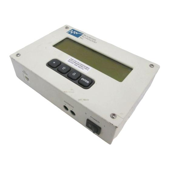
(such as the SENTRY 1000) for changing the set point and reading actual process exhaust values. It can be configured at the PTI factory to be used with controllers that maintain constant pressure or constant flow. It can be operated in... - Page 2 1.2 Part Descriptions Part Names – Supervisor Œ Œ Œ SENTRY Supervisor The SENTRY Supervisor is a microprocessor-based • interface used in conjunction with the Ž SENTRY exhaust controllers (SENTRY 1000, 1510, and 9000). The SENTRY • Supervisor provides the user with the...
- Page 3 1.1 Part Descriptions Part Names – Display Œ • Ž • • ‘ ’ StptMode Single Pres S 1700 Pres 1713 2000 Œ Œ Selection Indicator A star symbol • • Process Exhaust (Actual) Read- “*” will appear in the selection indicator Back The label “Pres”...
-
Page 4: Section 2: Installation & Power-Up
Section 2: Installation & Power-Up 2.1 Installation & Power-Up The SENTRY Supervisor is only one component of the SENTRY exhaust control system. Please follow the complete installation instructions for the specific controller to be installed in the controller manual included with the system. - Page 5 Supervisor is turned off. In order to permanently store selections into memory, the following steps must be taken. Œ Using the up [á] or down [â] arrow keys on the SENTRY Supervisor key pad, scroll through the menu parameters until “SAVE DATA” is shown in the top left corner of the display.
- Page 6 2.1 Installation & Power-Up Serial Communication Tool Interface (RS-422 or Optional RS-485) The SENTRY Supervisor supports an RS422/485 serial communication link for communication with a process tool or host computer. The Supervisor can be configured to operate using either a four-wire RS422 link or a two-wire RS485 link.
-
Page 7: Section 3: Command Menu
Section 3: Command Menu 3.1 The Command Menu The SENTRY Supervisor is common to all of the PTI automated exhaust controllers. As such, the Supervisor contains a number of command items which may not be applicable to the specific SENTRY system being installed. The complete menu is listed below. The menu contains 71 individual entries, 64 of which are directly accessible by the keyboard using the arrow keys. - Page 8 3.1 Command Menu Ref. # & Menu Item Function 14) Flow Sp1 For flow exhaust controllers, this is the entry that allows the flow set point to be reviewed or edited. 26) Pres FS For pressure exhaust controllers, this indicates the full pressure scale for the exhaust control device.
- Page 9 3.1 Command Menu Scaling Factors As indicated previously, the SENTRY Supervisor display and menu items do not show a decimal point. Depending on the SENTRY controller or menu parameter in question, a decimal point is implied in the displayed value.
-
Page 10: Section 4: Operation
Installation, Operation and Serial Communication Programmer’s Guide SENTRY™ Supervisor Section 4: Operation 4.1 Operation Manual Mode (Stand-Alone) Manual operation of the SENTRY controller is accomplished through the use of the SENTRY Supervisor key pad. The key pad is used to enter changes to the menu items available within the Supervisor. - Page 11 Refer to Section 2, page 2. for details. • The menu item “AUX IN” will reflect the voltage received at the SENTRY Supervisor. There is an implied decimal point to the left of the third digit (5000 = 5.000 volts).
- Page 12 Process exhaust flow set point: The set point voltage transmitted from the tool to set point voltage transmitted from the tool the SENTRY Supervisor will be converted to to the SENTRY Supervisor will be a pressure set point using the following...
-
Page 13: Section 5: Serial Communication Interface Programming
Section 5: Serial Communication Interface Programming 5.1 Serial Communication Interface Programming In order to configure a tool or host computer to communicate with the SENTRY Supervisor for adjusting a set point or interrogating a read-back value, the tool or computer must be programmed to communicate with the SENTRY Supervisor. - Page 14 Function: This response indicates an acknowledgement without error. Set Point Using Command “S” A set point command must be sent to the SENTRY Supervisor in order to command the process exhaust controller to a new set point. Depending on whether the exhaust controller is a pressure or flow controller, one of two memory locations must be addressed for this command.
- Page 15 = 000 to FFF representing a 0 to full scale range yy = two hex character check sum Function: This message sends a set point to a SENTRY Supervisor configured for pressure control (i.e. SENTRY 1000 or SENTRY 1510).
- Page 16 • Refer to Appendix C for error response codes. Actual Read-Back Using Command “L” A read-back command (interrogation) must be sent to the SENTRY Supervisor in order to request the actual process exhaust value. Depending on whether the exhaust controller is a pressure or flow controller, one of two memory locations must be addressed for this command.
- Page 17 5.1 Serial Communication Interface Programming Supervisor Normal Acknowledgment For both pressure and flow set point commands, the Supervisor responds with the following acknowledgment. Supervisor to Host Response: >A1xxxyy↵ Where: xxx = 000 to FFF representing a 0 to full scale range yy = two hex character check sum Function: This response indicates an acknowledgement with data but without error.
-
Page 18: Section 6: Troubleshooting, Specifications, Codes & Conversion Tables
Conversion Tables Troubleshooting Maintenance No maintenance is required to maintain the SENTRY Supervisor in working order. Troubleshooting The following troubleshooting table will assist the user in identifying and correcting some of the most common problems. Refer to the controller’s installation and operation manual for a complete guide. - Page 19 The booster fan includes a fuse for similar protection. AC disconnect device The SENTRY Supervisor relies upon the process tool or house facility for AC mains disconnect and start/stop device. Operating environment: Ambient temperature 40-104°...
- Page 20 Two-pass with a two character checksum for message transactions. Host initiates transaction by sending a command to one of the SENTRY Supervisor units on the network. The addressed Unit verifies that the command is valid and then executes the command.
- Page 21 "Power-Up Clear" command. The next command will then be executed normally. IMPORTANT: If this message is received it means that the SENTRY Supervisor has gone through its power-up sequence and has reset all characteristics to the last saved version. It may be necessary to reinitialize the controller.
-
Page 22: Conversion Tables
Conversion Tables Hex to ASCII Character Conversion Table Character Character Character Ctrl-@ Ctrl-A Ctrl-B Ctrl-C Ctrl-D Ctrl-E Ctrl-F Ctrl-G Ctrl-H Ctrl-I Ctrl-J Ctrl-K Ctrl-L < Ctrl-M Ctrl-N > Ctrl-O Ctrl-P Ctrl-Q Ctrl-R Ctrl-S Ctrl-T Ctrl-U Ctrl-V Ctrl-W Ctrl-X Ctrl-Y Ctrl-Z Ctrl-[ Ctrl-\ Ctrl-]... - Page 23 6.4 Conversion Tables Hex to Binary Conversion Table Binary Decimal 0000 0001 0010 0011 0100 0101 0110 0111 1000 1001 1010 1011 1100 1101 1110 1111 12279 Rev 1.0 Page 6 of 6...
-
Page 24: Section 7: Technical Support & Warranty Policy
The model number, serial number and revision reference of each component may be found on the SENTRY controller and SENTRY Supervisor serial tags. The model number and revision reference of the cables may be found as a label on each cable. For your convenience, please note the numbers below and retain this manual and information for future reference. -
Page 25: Warranty Policy
PTI factory. If within the period of this warranty, the equipment should fail due to such a defect, the customer should call the PTI factory to obtain a return authorization number and return the defective system to the PTI factory. The customer shall be responsible for returning the product to PTI in a condition that is free of any residual process chemicals, gasses, deposits or other materials that are hazardous to human contact.
Need help?
Do you have a question about the SENTRY Supervisor and is the answer not in the manual?
Questions and answers