Table of Contents
Advertisement
Advertisement
Table of Contents

Related Manuals for Givi Misure THESI 320

Summary of Contents for Givi Misure THESI 320
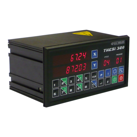
- Page 1 User Manual Position Controller www.givimisure.it...
-
Page 2: Table Of Contents
USER MANUAL POSITION CONTROLLER THESI 320 TABLE OF CONTENTS PRELIMINARY REMARKS INSTALLATION DIMENSIONAL SPECIFICATIONS REAR PANEL - CONNECTIONS KEY - MESSAGES AND SIGNALING DATA AND PROGRAMS RETENTION OPERATING INSTRUCTIONS CONFIGURATION PARAMETERS SETTING MACHINING PROGRAMS MANUAL OPERATION SEMI-AUTOMATIC OPERATION AUTOMATIC OPERATION... -
Page 3: Preliminary Remarks
USER MANUAL POSITION CONTROLLER THESI 320 PRELIMINARY REMARKS GIVI MISURE would like to thank you for purchasing the programmable position controller MICROCOMPUTER and confirms the excellent choice made. Thanks to a powerful microcontroller, the instrument is completely programmable by keyboard. -
Page 4: Installation
USER MANUAL POSITION CONTROLLER THESI 320 INSTALLATION W A R N I N G ! It is forbidden to switch on the instrument unless the machine on which it is installed conforms to 2006/42/EC Directive. All of the equipments connected to the instrument must have insulation characteristics in compliance with the regulations in force. -
Page 5: Dimensional Specifications
USER MANUAL POSITION CONTROLLER THESI 320 CLEANING The front panel can be cleaned only after disconnecting power supply, using a moist cloth. The instrument is not protected against liquid penetration. DO NOT USE SOLVENTS. MAINTENANCE Not required. DIMENSIONAL SPECIFICATIONS 15,5... -
Page 6: Rear Panel - Connections
USER MANUAL POSITION CONTROLLER THESI 320 REAR PANEL - CONNECTIONS LEGEND: = Ground connection = Power supply from 90 Vac to 230 Vac ± 10% - 50/60 Hz (or 24 Vac ± 10% - 50/60 Hz) MACHINE INPUT START = START input... - Page 7 USER MANUAL POSITION CONTROLLER THESI 320 MACHINE OUTPUT M-S / A = MANUAL-SEMI-AUTOMATIC / AUTOMATIC contact OK.POS = OK POSITION contact END PROG = END PROGRAM contact = AUXILIARY contact X / Y OUTPUT EN.MOV. = MOVEMENT ENABLE contact SLOW / AV = SLOW (DI) contact or ±...
- Page 8 USER MANUAL POSITION CONTROLLER THESI 320 CONNECTIONS Pag. 8/60 MT02_A41_A_TH320_GIVI_ENG rev. E...
-
Page 9: Key - Messages And Signaling
USER MANUAL POSITION CONTROLLER THESI 320 KEY – MESSAGES AND SIGNALING The following keys and symbols are used in this manual, with the following meaning: NUMERICAL KEYS FOR DIGIT ENTRY …. KEYS USED ALSO FOR SLOW FEED / BACK MOVEMENTS IN... - Page 10 USER MANUAL POSITION CONTROLLER THESI 320 KEY USED TO SELECT X AXIS KEY USED TO SELECT Y AXIS FLASHING VALUE STEADY VALUE The instrument provides a series of visual signals to support the user during configuration and use. Wrong operations are signaled with the following message:...
-
Page 11: Data And Programs Retention
USER MANUAL POSITION CONTROLLER THESI 320 DATA AND PROGRAMS RETENTION When the mains power supply is disconnected, the instrument can retain in its memory all the data and programs set. When powered off, the instrument can also store the last axis counting position. -
Page 12: Operating Instructions
USER MANUAL POSITION CONTROLLER THESI 320 OPERATING INSTRUCTIONS CONFIGURATION PARAMETERS Some internal parameters are used for the instrument configuration. To recall configuration, it is necessary to press the CONFIGURATION key for 2 seconds, enter the password and confirm with the ENTER key. - Page 13 USER MANUAL POSITION CONTROLLER THESI 320 Parameter 23 – SETTING OF FAST MOVEMENT ± 10 V OUTPUT PERCENTAGE Parameter 24 – MM/INCH CONVERSION Parameter 25 – SELECTING “POSITION WITH ACC./DEC. RAMPS” OPTION Parameter 26 – SETTING OF ACCELERATION TIME Parameter 27 – SETTING OF DECELERATION TIME Parameter 80 –...
- Page 14 USER MANUAL POSITION CONTROLLER THESI 320 If previously selected, the instrument goes automatically to the parameter setting for the Y axis. Set the parameter configuration, following the instructions provided below in the manual. d i r - to confirm the value and go back...
- Page 15 USER MANUAL POSITION CONTROLLER THESI 320 All the settings for the configuration of the position controller are described below: Parameter 01 – POSITION PRESET The parameter is used to set the real positions of the axes. Example of value setting X= 50.0 mm...
- Page 16 USER MANUAL POSITION CONTROLLER THESI 320 d i r - to confirm the selection and Press P 02 enter its settings d i r - d i r - Press to invert the counting direction P 02 - d i r...
- Page 17 USER MANUAL POSITION CONTROLLER THESI 320 Example: CF value setting = 1.25000 on X and Y axes 1.0 0 0 0 0 to select the parameter Press 1.0 0 0 0 0 P 03 (see PARAM. SELECTION) 1.0 0 0 0 0...
- Page 18 USER MANUAL POSITION CONTROLLER THESI 320 C n t n 4 to confirm and go back to Press parameters selection P 04 5 0.0 to quit configuration and go back Press 2 0 0.0 to the positions display Parameter 05 – DECIMAL POINT POSITION (0, 1, 2, 3) With this parameter, it is possible to select the number of decimals that will be shown on the axis display.
- Page 19 USER MANUAL POSITION CONTROLLER THESI 320 Parameter 06 – AXIS RESOLUTION This parameter allows to select the axis resolution, based on the number of pulses of the encoder (PPR). The resolutions that can be set are: 200 – 100 – 50 – 20 – 10 – 5 – 2 – 1 µm 0.01 –...
- Page 20 USER MANUAL POSITION CONTROLLER THESI 320 Example of value setting X axis = 0.0 mm Y axis = -50.0 mm to select the parameter Press P 07 (see PARAM. SELECTION) Press to select both axes P 07 0 0 0 0 0.0...
- Page 21 USER MANUAL POSITION CONTROLLER THESI 320 0 0 0 0 0.0 to confirm the selection and Press enter the X axis setting P 08 Enter the desired value and align it to the decimal point displayed. 3 0 0.0 to confirm the value and...
- Page 22 USER MANUAL POSITION CONTROLLER THESI 320 to confirm the value and go back Press to parameters selection 1 5.0 P 09 5 0.0 to quit configuration and go back Press to the positions display 2 0 0.0 Parameter 10 – SETTING OF MECHANICAL BACKLASH RECOVERY VALUE If positive, the value of mechanical backlash recovery is executed in positive direction;...
- Page 23 USER MANUAL POSITION CONTROLLER THESI 320 Parameter 11 – SETTING OF SPEED CHANGE VALUE The speed change value is used to switch from fast to slow movement, during positioning. If speed change is not required, enter a value of 0. In this case, positioning will be made only at slow speed.
- Page 24 USER MANUAL POSITION CONTROLLER THESI 320 Example of value setting X axis = 0.8 mm Y axis = 1.0 mm to select the parameter Press P 12 (see PARAM. SELECTION) Press to select both axes P 12 0 0 0 0 0.0...
- Page 25 USER MANUAL POSITION CONTROLLER THESI 320 Enter the desired value and align it to the decimal point displayed. to confirm the value and Press P 13 enter the Y axis setting 0 0 0 0 0.0 Enter the desired value and align it to the decimal point displayed.
- Page 26 USER MANUAL POSITION CONTROLLER THESI 320 5 0.0 to quit configuration and go back Press to the positions display 2 0 0.0 Parameter 15 – SETTING OF DEVIATION VALUE With this parameter, it is possible to set the position deviation value to be applied at the closure of the related input.
- Page 27 USER MANUAL POSITION CONTROLLER THESI 320 0.0 0 Press to select both axes 0.0 0 P 16 0 0 0 0.0 0 to confirm the selection and Press enter the X axis setting 0.0 0 P 16 Enter the desired value and align it to the decimal point displayed.
- Page 28 USER MANUAL POSITION CONTROLLER THESI 320 Enter the desired value and align it to the decimal point displayed. 0.3 0 to confirm the value and go back Press to parameters selection 0.5 0 P 17 5 0.0 to quit configuration and go back Press 2 0 0.0...
- Page 29 USER MANUAL POSITION CONTROLLER THESI 320 to confirm the selection and Press enter its settings P 19 y E S Press to choose the desired selection P 19 y E S to confirm and go back to Press P 19 parameters selection 5 0.0...
- Page 30 USER MANUAL POSITION CONTROLLER THESI 320 Parameter 21 – SELECTING “REQUESTED POSITIONING DISPLAY” OPTION This parameter allows to enable/disable the displaying of the required position instead of the real position, at the end of a positioning within the tolerance range.
- Page 31 USER MANUAL POSITION CONTROLLER THESI 320 Enter the desired percentage value. to confirm the value and Press P 22 enter the Y axis setting 0 0 0 0 0 0 Enter the desired percentage value. to confirm the value and go back...
- Page 32 USER MANUAL POSITION CONTROLLER THESI 320 5 0.0 to quit configuration and go back Press to the positions display 2 0 0.0 Parameter 24 – MM/INCH CONVERSION With this parameter, it is possible to select the unit of measurement (mm or inches) with which the axes positions are displayed.
- Page 33 USER MANUAL POSITION CONTROLLER THESI 320 y E S Press to choose the desired selection P 25 y E S to confirm and go back to Press parameters selection P 25 5 0.0 to quit configuration and go back Press 2 0 0.0...
- Page 34 USER MANUAL POSITION CONTROLLER THESI 320 Note: setting at 0 the value of the time of parameter 27, it is possible to operate with a deceleration based only on the space available for changing speed. In the figure below, it is possible to find a representation of the acceleration ramp and a...
- Page 35 USER MANUAL POSITION CONTROLLER THESI 320 Enter the desired value and align it to the decimal point displayed. 0.6 0 to confirm the value and go back Press to parameters selection 0.6 0 P 26 5 0.0 to quit configuration and go back Press 2 0 0.0...
- Page 36 USER MANUAL POSITION CONTROLLER THESI 320 Parameter 80 – PARAMETERS’ ACCESS PASSWORD MODIFICATION The default password set by the Manufacturer is “000000”. The password can be modified, to make parameters’ configuration accessible only to authorized personnel. Example of setting 0 0 0 0 0 0...
- Page 37 USER MANUAL POSITION CONTROLLER THESI 320 2) Keyboard test C o d E the code of the pressed key will Press 0 0 0 P 89 be displayed Press all the keys. To each key will correspond a code, as shown in the table below:...
- Page 38 USER MANUAL POSITION CONTROLLER THESI 320 5) Led test the axis and keyboard led will be Press P 89 switched on in sequence 6) Inputs and auxiliary outputs test 0 0 0 0 0 0 to see the status of the inputs...
- Page 39 USER MANUAL POSITION CONTROLLER THESI 320 In this phase, it is possible to test also the auxiliary outputs (AUX, END PROG, OK POS, etc.). To check the ON/OFF status of the outputs, press the corresponding key: Press to switch the AUX output (MACHINE OUTPUT)
-
Page 40: Setting Machining Programs
USER MANUAL POSITION CONTROLLER THESI 320 SETTING MACHINING PROGRAMS position controller can store up to 99 machining programs, containing up to 20 positions of the axes each. To each position it is possible to link up to 99 repetitions. Each position and the related repetitions form a program cycle that can be executed in the semi-automatic operation mode. - Page 41 USER MANUAL POSITION CONTROLLER THESI 320 5 0.0 to confirm the value and go on Press setting the Y axis 0 0 0 0 0.0 01 02 5 0.0 Enter the value of the Y axis position, aligning it to the 0 0 1 0 0.0...
- Page 42 USER MANUAL POSITION CONTROLLER THESI 320 2 5 0.0 Enter the value of the Y axis position, aligning it to the 0 0 3 0 0.0 02 02 decimal point displayed to confirm the value and go on Press setting the repetitions 02 02 Enter the number of repetitions (8).
- Page 43 USER MANUAL POSITION CONTROLLER THESI 320 The number of the first available program will flash (e.g. program 01). 5 0.0 to quit machining program Press setting 2 0 0.0 Notes: 1) To cancel an entire machining program, go on the first cycle in “program view” mode and press the CLR key for 4 seconds.
- Page 44 USER MANUAL POSITION CONTROLLER THESI 320 If the positions, the repetitions or the status of the AUX outputs of a cycle are to be modified, select the concerned value. 4 5 0.0 to go back to the program cycles Press 5 0 0.0...
-
Page 45: Manual Operation
USER MANUAL POSITION CONTROLLER THESI 320 MANUAL OPERATION When switched on, the position controller sets itself for manual operation and only the axis displays turn on. In this operating mode, the axis movement can be controlled with the following keys:... -
Page 46: Semi-Automatic Operation
USER MANUAL POSITION CONTROLLER THESI 320 SEMI-AUTOMATIC OPERATION Semi-automatic operation allows for a single automatic positioning of the axes. It is possible to switch from manual to semi-automatic operation by selecting the axes to be positioned, pressing the corresponding key, entering the arrival positions and, eventually, the number of repetitions (1-99) that will be counted once positioning has been executed. - Page 47 USER MANUAL POSITION CONTROLLER THESI 320 to confirm and proceed with the Press Y axis programming o F F to program the ON status of the Press o n * Y axis output POINT (1) x x x.x to start positioning. The led of...
- Page 48 USER MANUAL POSITION CONTROLLER THESI 320 Notes: 1) The position controller does not accept the programming of a position outside the measuring length limits set. 2) If positioning cannot be completed correctly (due to an erroneous configuration of parameters, such as inertia, speed change, tolerance, etc.), after three attempts the instrument stops and signals the erroneous position with the flashing of the START key led.
-
Page 49: Automatic Operation
USER MANUAL POSITION CONTROLLER THESI 320 AUTOMATIC OPERATION With the automatic operation mode it is possible to run previously stored programs. Example of immediate running of program 02 5 0.0 to enter the selection of the Press 2 0 0.0... - Page 50 USER MANUAL POSITION CONTROLLER THESI 320 4 5 0.0 to go back to the selection of a Press 5 0 0.0 new program to run 01 02* 4 5 0.0 to quit automatic operation and Press 5 0 0.0 go back to manual operation Notes: 1) Before running a program, it is possible to display its cycles.
-
Page 51: Inputs
USER MANUAL POSITION CONTROLLER THESI 320 INPUTS START The START input is used to start positioning from the outside in the same way as the START key in the front panel. Connect a N.O. contact between the START input and COM+. -
Page 52: Outputs
USER MANUAL POSITION CONTROLLER THESI 320 PRESET X / Y The PRESET input is used to set, on the axis display, a position value previously programmed in the configuration parameters (see parameter 09). The input works in combination with the ZERO ENCODER input, as follows: if the ZERO ENCODER input is not connected, when the PRESET input closes, the value is loaded immediately;... - Page 53 USER MANUAL POSITION CONTROLLER THESI 320 SLOW / FAST The SLOW / FAST outputs are used to control the axes movements in the two speeds, in any of the operating modes: manual/semi-automatic/automatic. The outputs correspond to N.O. relay contacts connected to their common COM FS; they alternatively close to command the axis movement and they open to terminate the movement.
-
Page 54: Additional Information
USER MANUAL POSITION CONTROLLER THESI 320 ADDITIONAL INFORMATION CONFIGURATION PARAMETERS: MEMO PARAMETER DESCRIPTION VALUE X VALUE Y POSITION PRESET INVERSION OF COUNTING DIRECTION ENCODER PULSE CORRECTION COUNTING MODE DECIMAL POINT POSITION AXIS RESOLUTION MINIMUM MEASURING LENGTH LIMIT MAXIMUM MEASURING LENGTH LIMIT... -
Page 55: Technical Characteristics
USER MANUAL POSITION CONTROLLER THESI 320 TECHNICAL CHARACTERISTICS THESI 320 Model 2 DISPLAY - 2 ENCODER INPUTS POSITION = 6 high-efficiency digits h = 13 mm and negative sign Display CYCLES / PROGRAMS = 2+2 high-efficiency digits h = 13 mm 2 square waves with phase displacement of 90°... -
Page 56: Warranty Terms
USER MANUAL POSITION CONTROLLER THESI 320 WARRANTY TERMS The position controller is guaranteed against manufacturing faults for a period of twelve months from the date of purchase. Any repair must take place at the Manufacturer’s premises and the Customer shall arrange the delivery of the product, at its own risk and expense. -
Page 57: Notes
USER MANUAL POSITION CONTROLLER THESI 320 NOTES Pag. 57/60 MT02_A41_A_TH320_GIVI_ENG rev. E... - Page 58 USER MANUAL POSITION CONTROLLER THESI 320 NOTES Pag. 58/60 MT02_A41_A_TH320_GIVI_ENG rev. E...
- Page 59 USER MANUAL POSITION CONTROLLER THESI 320 NOTES Pag. 59/60 MT02_A41_A_TH320_GIVI_ENG rev. E...
- Page 60 ROTARY ENCODERS DIGITAL READOUTS POSITION CONTROLLERS GIVI MISURE S.r.l. A SOCIO UNICO Via Assunta, 57 - 20834 Nova Milanese (MB) - Italy C.F. e Iscrizione al Reg. Imprese di Monza e Brianza n° 04355540156 - Cap. Soc. € 51.480,00 I.V.
Need help?
Do you have a question about the THESI 320 and is the answer not in the manual?
Questions and answers