Table of Contents
Advertisement
Advertisement
Table of Contents

Related Manuals for AMI 205

Summary of Contents for AMI 205
- Page 1 Model 205 Tube Welding Power Supply Operator’s Manual Part No. 740108 Revision J...
-
Page 2: Introduction
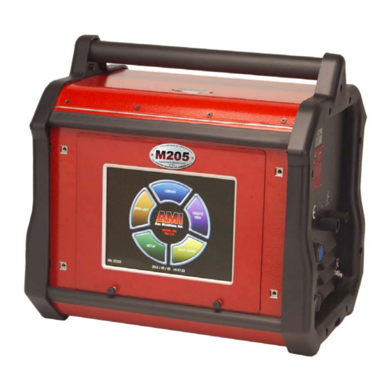
M A N U A L INTRODUCTION he Model 205 is a power source and controller for automatic orbital tube welding. It is intended to be used only in conjunction with AMI or EXEL orbital tube weldheads. The Model 205 power supply provides GTAW (Gas Tungsten Arc Welding) current with pulsation controls, high frequency arc starting, purge gas controls, weldhead arc rotation and automatic timing functions. -
Page 3: Revision History
M O D E L 2 0 5 O P E R A T O R ’ S M A N U A L Revision History Rev ECO No. Change Description Date Appr. Initial release 3/10/09 B.F. 5355 Update sections 2.0, 3.0, 4.0, 5.0 & 6.0; delete Glossary 5/14/09 B.F. -
Page 4: Table Of Contents
INSPECTION ..................10 POWER CONNECTION............... 11 WELDING GAS CONNECTIONS ............11 MODEL 205 TO M8 / M9 WELDHEAD HOOK UP ......12 MODEL 205 TO EXEL ROTOR DRIVER HOOK UP......16 MODEL 205 TO M21 WELDHEAD HOOK UP ........17 OPERATION.................. -
Page 5: Safety Precautions
M A N U A L 1.0 SAFETY PRECAUTIONS The Model 205 is intended to be used only with AMI or EXEL weldheads for the purpose of GTAW welding of metal tube. The system is not to be used for any other purpose, specifically heating or cutting. - Page 6 USER MUST OBSERVE COMMON SAFETY PRACTICES such as grounding the electrode to ensure discharge before actually touching it. Most AMI Power Supplies feature High Frequency (HF) Arc Starting. This is a High Voltage/High Frequency electrical transmission process. To eliminate any HF shock possibility “AVOID ALL CONTACT”...
-
Page 7: Warning Label Definitions
M O D E L 2 0 5 O P E R A T O R ’ S M A N U A L 1.2 WARNING LABEL DEFINITIONS The table below contains caution and warning labels for the operation of this equipment. Before operating this or any welding equipment users should be familiar with ANSI-49.1 Safety in Welding and Cutting. - Page 8 M A N U A L MOVING PARTS - Keep hands and fingers clear of fans, gears, rotors, wire feed, rotation and AVC mechanisms WARNING: AMI factory training is essential for all Welding Operators and Maintenance Technicians who operate AMI equipment.
-
Page 9: Specifications
For non-AMI supplied equipment such as gas tanks and regulators, refer to the original manufacturer’s documentation. The Model 205 is a mobile system that is intended be hand carried. The supporting equipment such as weldheads, water coolers, gas regulators, remote controls and extension cables can also be hand carried. -
Page 10: Electical Service Guide
CIRCUIT BREAKER – ON/OFF, two pole, 20 Ampere at 250 VAC. DUTY CYCLE – determined by the AC input voltage and the required output current. The Model 205 system has an internal thermal sensor that will limit operation should the temperature exceed the safe operating parameters. -
Page 11: Programmable And Operational Functions
M O D E L 2 0 5 O P E R A T O R ’ S M A N U A L 2.4 PROGRAMMABLE AND OPERATIONAL FUNCTIONS SINGLE ENTRY FUNCTIONS FUNCTION RANGE PREPURGE 5.0 – 999.0 seconds POSTPURGE 5.0 –... -
Page 12: Initial Setup
This manual is intended to assist users of this equipment in set up and basic operation. It is NOT INTENDED AS A SUBSTITUTE FOR FACTORY TRAINING. 3.1 SYSTEM SYMBOLS The following symbols are present on the Model 205 version 13B050100-02 Revision NC and up: WARNING: Read this manual! This document contains information that could help prevent injury or damage to the equipment. - Page 13 ARC GAS OUTPUT - output for the arc shielding gas connection. WELDHEAD CONTROL - weldhead motor control. Intended for AMI and EXEL weldheads only. The optional water cooler M205-CW is marked with the following symbols: WATER RETURN - cooling water input.
-
Page 14: Inspection
M A N U A L 3.2 INSPECTION The Model 205 is shipped with a variety of peripheral equipment such as gas hoses, fittings and cables. An exact list of these items is included with each power supply shipment and should be located prior to setup. -
Page 15: Power Connection
Provided the input voltage is within this range, the unit will automatically adjust for the input voltage. 1. The Model 205 is supplied with a 15 foot power cord. A suitable AC line connector matching the input power must be supplied and installed by the user. Color coding of... -
Page 16: Model 205 To M8 / M9 Weldhead Hook Up
O P E R A T O R ’ S M A N U A L 3. The arc gas is controlled by a solenoid and flow sensor in the Model 205. Attach the input gas line to ARC GAS INPUT fitting on the Model 205, NOT DIRECTLY TO THE WELDHEAD. - Page 17 5. Insert the male gas quick-disconnect fitting on the weldhead to the mating ARC GAS OUTPUT connector on the Model 205 and hand-tighten the lock screw to prevent accidental disconnection. Slide the rubber boot over the connection. Adapter Cable Connections 1.
- Page 18 7. Insert the male gas quick-disconnect fitting on the adapter cable to the mating ARC GAS OUTPUT connector on the Model 205 and hand-tighten the lock screw to prevent accidental disconnection. Slide the rubber boot over the connection. Fig. 1...
- Page 19 M O D E L 2 0 5 O P E R A T O R ’ S M A N U A L Fig. 2 Hookups for Liquid Cooled Weldheads...
-
Page 20: Model 205 To Exel Rotor Driver Hook Up
Always turn the power supply off before making any cable or connection changes to the power supply. The EXEL rotor driver (Model RDR-005) connects directly to the Model 205. The rotor driver has NO connections to the M205-CW Cooling Unit. -
Page 21: Model 205 To M21 Weldhead Hook Up
O P E R A T O R ’ S M A N U A L 3.7 MODEL 205 TO M21 WELDHEAD HOOK UP Always turn the power supply off before making any cable or connection changes to the power supply. -
Page 22: Operation
• LIBRARY - The heart of the Model 205 is its MEMORY. The values of each parameter for a given weld are only programmed one time. After that the Model 205 will store the parameter values by schedule NAME, DIAMETER, WALL thickness, and MATERIAL. - Page 23 This data is feedback data from both the Travel and Current servos and is recorded every 0.1 second. This data is saved to the hard drive of the Model 205 as a Weld Data Record. The name of the Weld Data Record is a concatenation of the Power Supply &...
-
Page 24: Initial Power On
Model 205. Move the circuit breaker to the ON position. 3. If the Model 205-CW is installed connect the AC cord to 110 or 220 VAC, single phase power. Set the ON/OFF switch to the ON position. -
Page 25: Set-Up Functions
PASSWORD SETTING The Model 205 can be set up to require a password entry to use the machine. Your unit is shipped to you with no password requirement. 1. OPERATOR: An Operator may load and run any weld schedule but may... - Page 26 NEW PASSWORD fields will delete the password. TO RESTORE A PASSWORD: 1. If you have lost or forgotten your password contact AMI Service Department to obtain a one-day password. This will restore access to the unit and allow you to set up new passwords.
- Page 27 LANGUAGE UPDATE Customizing a pre-programmed language or creating a language from a pre-programmed language: 1. Insert a USB memory stick in the Model 205 USB port. 2. From the HOME screen press SETUP. 3. From the SETUP screen press ADD LANGUAGE.
- Page 28 Open screen displays, select the language file in the external memory to be added (*.lgv file). 6. Press OK. When adding a language from external memory the language MUST be formatted for the Model 205 software otherwise the screens will be corrupted when this language is selected.
-
Page 29: Opening The Last Weld Schedule
M O D E L 2 0 5 O P E R A T O R ’ S M A N U A L 4.4 OPENING THE LAST WELD SCHEDULE OPENING THE LAST WELD SCHEDULE OPENING THE LAST WELD SCHEDULE OPENING THE LAST WELD SCHEDULE Skip to Step 4.8 if no weld schedules are stored in the library. -
Page 30: Modify A Weld Schedule
M O D E L 2 0 5 O P E R A T O R ’ S M A N U A L Note Use the UP or DOWN arrows to find additional weld schedules. Note You may search for and segregate weld schedules by DIAMETER, WALL or MATERIAL. Select one or more of these categories from the 3 drop-down lists, select the weld schedule, then press LOAD. - Page 31 M O D E L 2 0 5 O P E R A T O R ’ S M A N U A L 2. From the RUN screen press SCHEDULE. 3. The first parameters displayed are the SINGLE ENTRY parameters. The MULTI- LEVEL parameters and ASSOCIATED DATA parameters are accessed by using the NEXT button on each screen.
- Page 32 M O D E L 2 0 5 O P E R A T O R ’ S M A N U A L Multi-Level Parameters: Associated Data Parameters: 4. Select each field to be modified and enter the text or value via the on-screen alpha- numeric keyboard or 10-key pad, then press the RETURN or ENTER key.
- Page 33 M O D E L 2 0 5 O P E R A T O R ’ S M A N U A L Note If the +1% or -1% button is pressed on the Multi Level screen the Primary Amps will be incremented or decremented by this percentage.
-
Page 34: Copy A Weld Schedule
M A N U A L 4.7 COPY A WELD SCHEDULE The Model 205 has the ability to make a copy of a weld schedule and save it under a new name in the Model 205 Library. You may also copy one or all weld schedules stored in the Model 205 Library and save them to a USB Memory stick, or copy one or all weld schedules on a USB memory stick and save them to the Model 205 Library. - Page 35 M A N U A L • View Weld Schedules Stored On a USB Stick 1. Insert a USB memory stick into the USB port on the Model 205. 2. From the HOME screen press LIBRARY. 3. From LIBRARY press VIEW USB.
- Page 36 O P E R A T O R ’ S M A N U A L • Copy one or all weld schedules from a USB memory stick to the Model 205 Library 1. Insert a USB memory stick into the USB port on the Model 205.
-
Page 37: Create A Weld Schedule
O P E R A T O R ’ S M A N U A L 4.8 CREATE A WELD SCHEDULE The Model 205 provides two versions of manual weld schedule creation: Manual Multi level and Manual S (Single Level Sloped) and four versions of Automatic weld schedule generation: Auto Continuous Travel, Auto Stepped Travel, Auto Tack, and Auto S 1. - Page 38 M O D E L 2 0 5 O P E R A T O R ’ S M A N U A L 6. The welding parameters may now be entered manually by selecting either MANUAL MULTI or MANUAL S , or a weld schedule may be automatically generated by selecting AUTO CONTINUOUS TRAVEL, AUTO STEPPED TRAVEL, AUTO TACK, or AUTO S...
-
Page 39: Weldhead Calibration
M O D E L 2 0 5 O P E R A T O R ’ S M A N U A L • Auto S – this version of automatic programming will generate a single-level program that continually ramps the current down over the course of the weld. This ramping is established by programming a starting amps (START AMPS) and an ending amps (END AMPS). -
Page 40: Performing A Weld
M O D E L 2 0 5 O P E R A T O R ’ S M A N U A L If an adjustment to the weldhead’s calibration potentiometer is required the screen will display CALIBRATION FAILED – TURN TRIM POT CCW – TRY AGAIN CALIBRATION FAILED –... - Page 41 M A N U A L 6. The Model 205 features a WELD/TEST button. In the TEST mode the unit will allow for electrode rotation but will not strike an arc. The WELD or TEST font on the button turns yellow to indicate which mode the system is set to.
- Page 42 M O D E L 2 0 5 O P E R A T O R ’ S M A N U A L 9. Once the operator manually presses the START button the following events will occur automatically: • EVENT 1: PREPURGE - welding gas will start to flow and continue to flow for the entire weld sequence from the gas source through the power supply to the weldhead.
- Page 43 M O D E L 2 0 5 O P E R A T O R ’ S M A N U A L Note The electrode rotation direction is a Single Entry function and cannot be programmed to change direction during a weld. •...
-
Page 44: Weld Data Recording
M O D E L 2 0 5 O P E R A T O R ’ S M A N U A L 4.11 4.11 4.11 4.11 WELD DATA RECORDING WELD DATA RECORDING WELD DATA RECORDING WELD DATA RECORDING •... - Page 45 The font on the WDR button turns while the weld data is being recorded. • Export Weld Data Record 1. Insert a USB memory stick into the USB port on the Model 205. 2. Press WDR to return to the Weld Data Recording screen.
- Page 46 M O D E L 2 0 5 O P E R A T O R ’ S M A N U A L 3. Press EXPORT WDR FILE to select a WDR file and an export destination. 4. Press OK Note The OK button will ONLY be enabled when BOTH the Source and Destination fields are filled.
-
Page 47: Maintenance And Trouble-Shooting
Always disconnect the AC power cable from the line voltage before attempting to work with this welding power supply. 5.1 GENERAL MAINTENANCE • COOLANT - the water tank in the optional Model 205- cooling unit holds approximately 0.75 gallons (2.8 liters) of fluid. Check the fluid level periodically. The use of different weldheads will remove fluid from the tank over a period of time. - Page 48 Always disconnect the power input cable from the junction box or wall-plug before cleaning. DO NOT USE acid, corrosives or any liquid substance on the Model 205 or any AMI weldhead. When cleaning use only a light solution of isopropyl alcohol on a soft cloth.
- Page 49 1 mega ohm input impedance. Battery operated devices are recommend. Suggested: Fluke Model 8060A or equivalent. • AMI Fusion Weldhead rated for 150 amperes and a pipe or tube that will not melt away with 150 amps applied. As an alternative a manual torch can be set up on a flat plate (refer to Section 5.2.2).
- Page 50 M O D E L 2 0 5 O P E R A T O R ’ S M A N U A L PROCESS A weld schedule is required for calibration and will need to be created the first time a calibration is done.
- Page 51 M O D E L 2 0 5 O P E R A T O R ’ S M A N U A L 3. From the HOME screen press SETUP 4. From the SETUP screen press ADVANCED.
- Page 52 Note To prevent unauthorized personnel from accessing the calibration feature a temporary one-day password is required. Contact the AMI Service department for this password. You will need the Power Supply serial number displayed on the HOME screen to obtain this password.
- Page 53 M O D E L 2 0 5 O P E R A T O R ’ S M A N U A L 8. The START button is located in the upper right corner of the screen. Once you have determined it is safe to initiate an arc press START.
- Page 54 O P E R A T O R ’ S M A N U A L 5.3 TROUBLESHOOTING The Model 205 has the ability to monitor certain functions. If they are not working correctly a system fault will alert the operator to the problem. SYSTEM FAULT CORRECTIONS When a System Fault occurs prior to or during welding it is required for the operator to clear the fault condition before continuing.
- Page 55 • BAD START - if for any reason the Model 205 cannot establish a stable arc at the end of Prepurge the system will display a BAD START fault. There can be several reasons for this to occur.
-
Page 56: Options
M A N U A L 6.0 OPTIONS The following are installation and operation instructions for Model 205 options. Some options have their own manuals and these are not discussed in this section. Always turn the power supply OFF before making any cable or connection changes to the Model 205 power supply. - Page 57 2. Before mounting the Model 205-CW Cooling Unit to the Model 205 remove the fill cap and add the coolant mixture. Replace the fill cap. 3. Place the Model 205 onto the Model 205-CW Cooling Unit and close the latches on each end.
- Page 58 PURGE, and return to HOME of the weldhead rotor. • Attach the remote pendant connector to the REMOTE connector on the Model 205. Note the positioning keyway and NEVER FORCE or use tools on the cable connectors. Hand-tighten the connecting ring being careful not to cross-thread the ring.
- Page 59 M O D E L 2 0 5 O P E R A T O R ’ S M A N U A L...
Need help?
Do you have a question about the 205 and is the answer not in the manual?
Questions and answers