Table of Contents

Summary of Contents for Mission Communications PN OP750
- Page 1 Expansion New! Modules PMS 660 Installation Manual PN OP750 Safe Module Plus PN OP464-30/31 Pulse Input (2 channels each, 4 total) PN OP653 Digital Input (8 channel, isolated) PN OP465 Analog Input (4-channel) PN OP461 Analog Output (2-channel)
- Page 2 Welcome, Thank you for choosing Mission Communications for your monitoring and alarm needs. Mission is committed to providing the highest quality of SCADA solutions. All products go through a strict testing regimen before leaving the facility to ensure a seamless installation experience.
-
Page 3: Table Of Contents
Chapter 2: Location Chapter 3: Communications Cable Chapter 4: Single Expansion Module Hookup Chapter 5: Pre-Installation Chapter 6: Safe Module Plus (PN OP750) Chapter 6.1: SMP Pulse Inputs Chapter 7: Pulse Input (PN OP464) Chapter 8: Digital Input (PN OP653) -
Page 4: Chapter 1: Overview
Chapter 1: Overview Expansion modules increase the monitoring possibilities of the MyDro remote terminal unit (RTU). Mission provides options for expanded input/output (I/O) based on ADVANTECH modules. The new Safe Module Plus expansion module brings useful features to sewer lift station monitoring, fresh water pump lock- out applications, and rain sensing applications. - Page 5 Table 1: Expansion module part numbers, functions, and power requirements. Max power* requirement of the Module does not include instrumentation. MyDro Dev ID On Main Expansion Expansion ADVANTECH PN Board Available I/O Power* Modules Decimal Safe Module 1 intrinsically safe float input Plus (presented OP750...
-
Page 6: Chapter 2: Location
Chapter 2: Location In most cases, the included 8-foot communications cable allows the expansion module(s) to be mounted on the back panel of the control cabinet and the other end connected to the nearby MyDro RTU. The expansion module(s) can be mounted on a DIN rail or directly to a backplate in the control cabinet. -
Page 7: Chapter 4: Single Expansion Module Hookup
Chapter 4: Single Expansion Module Hookup Avoid routing the communications cable parallel to other load carrying conductors. Figures 1A and 1B demonstrate a single module network powered by the communications cable. For an example of a multiple module hookup, see Appendix Figure 1A: Figure 1B: Safe Module Plus... -
Page 8: Chapter 5: Pre-Installation
Chapter 5: Pre-Installation Note: Electronic keys are supplied with each RTU. They can be configured at the web portal for a variety of functions (track site visits, acknowledge alarms, service mode, config. mode). For pre-installation, keys should have service and config mode privileges. 1. -
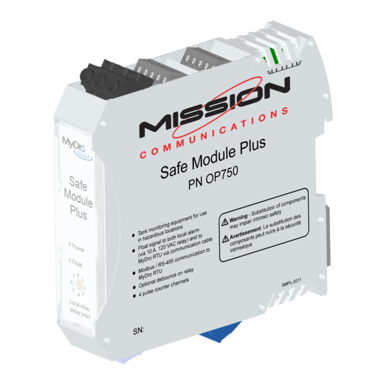
Page 9: Chapter 6: Safe Module Plus (Pn Op750)
Chapter 6: Safe Module Plus (PN OP750) Safe Module Plus Overview NEC Rule 22-704 The Safe Module Plus (SMP) is an exclusive device National Electric Code (NEC) that speeds and simplifies the installation of a Mission Rule 22-704 offers comprehensive MyDro 150 or 850 RTU. - Page 10 Sewer Lift Station Applications Figure 2: Sewer lift station application Float and Panel Wiring for Sewer Lift Station Applications The two-wire connection to the float is not polarity sensitive. Locate (or intercept if a retrofit application) the high-level float wires and terminate them on the SMP lower float terminals.
- Page 11 Service Pump Lock-Out Applications The relay can be used for other applications including fresh water applications requiring a pump lock-out. For example, a service pump drawing from a clear well, or below ground storage tank may be commanded to run by either local control or by the Mission Tank and Well Control Package (an automated remote- control system).
- Page 12 Debounce Turbulent waters near the tipping point of a float can result in rapid contact closure cycles. To reduce the side effects of this situation, two types of debounce are offered. First, the local relay can be set with a debounce by way of the front facing rotary switches.
- Page 13 1. Confirm with Mission Tech Support that MyDro has been paged to accept SMP. 2. The green LED on front panel of SMP should illuminate. 3. Tip the float. Use the touch screen to evaluate the state of DI 4. DI 4 on the MyDro Digital screen should illuminate.
-
Page 14: Chapter 6.1: Smp Pulse Inputs
Chapter 6.1: SMP Pulse Inputs The SMP supports four pulse inputs. They are generally used with rain tipping buckets and pulse flow meters. Changes to pulse readings are reported every 15 minutes for the MyDro 150 and every two minutes for the MyDro 850. The minimum pulse width is 16 milliseconds (8 milliseconds high and 8 milliseconds low). - Page 15 Chapter 6.2: SMP DIN Rail Mount and Release The SMP can be mounted on a DIN rail, placing the SMP onto the DIN rail and rotating down will engage the lower latch that will lock the SMP onto the DIN Rail. To remove the SMP from the DIN rail, insert a flat head screw driver into the open slot on the metal latch on the bottom back side of the enclosure, pull the latch down using the leverage of the screwdriver and rotate the enclosure upward and...
-
Page 16: Chapter 7: Pulse Input (Pn Op464)
Chapter 7: Pulse Input Expansion Module (PN OP464) The MyDro supports two Pulse Input Expansion Modules for a total of four channels. It is generally used with rain tipping buckets and pulse flow meters. Note: If used, the second Pulse Input Expansion Module must be ordered as PN OP464-31 so the device address is set to 31. - Page 17 Active Pulse Some flow meters source the voltage (active pulse). The Pulse Input Expansion Module supports up to 5 VDC wetted circuits (see Figure 5B). Polarity must be observed. Figure 5B: Active pulse wiring: Logic level 0: 0–0.8 V. Logic level 1:+2.4 V to 5 V D.GND is common to (Blk) GND terminal Flow meters that source voltages greater than 5 volts can be accommodated with a voltage divider circuit consisting of properly sized resistors (see Figure 5C).
-
Page 18: Chapter 8: Digital Input (Pn Op653)
Chapter 8: Digital Input Expansion Module (PN OP653) Eight digital inputs can be added to the MyDro (for a total of 16) with the Digital Input Expansion Module (see Figure 6). These inputs are logically treated as alarm inputs, meaning that changes in state are reported in real-time. They cannot be configured as pump start/runtime accumulators. -
Page 19: Chapter 9: Analog Input (Pn Op465)
Chapter 9: Analog Input Expansion Module (PN OP465) The Analog Input Expansion Module adds four analog inputs to the two that are on the mainboard. Analog values are reported every two minutes with the MyDro 850. Analog expansion is not supported with the MyDro 150. The module supports 4–20 mA current inputs or 0–5 volt inputs (see Table 4 and Figure 7). -
Page 20: Chapter 10: Analog Output (Pn Op461)
Chapter 10: Analog Output Expansion Module (PN OP461) The Analog Output Expansion Module adds two current loop, 4–20 mA output channels (see Figure 8). The output impedance of the Analog Output Expansion Module is 0.5 ohms. The maximum current load resistance is 500 ohms. Figure 8: Analog output current loop on output channel 2... -
Page 21: Appendix A: Upgrades From Legacy Rtus, Wet Well Modules
Appendix A: Upgrades from Legacy RTUs, Wet Well Modules, and Pulse Counter Expansion Boards Legacy series (M110, M800) RTUs supported a Wet Well Module (WWM) by way of an RJ45 interface on the left side of the printed circuit board. There were two versions of the WWM (generation 1—green and generation 2—red). -
Page 22: Appendix B: Troubleshooting
Appendix B: Troubleshooting Problem Probable Cause Solution Power LED not Communication cable Use VOM to check illuminated on expansion disconnected, mis-wired, voltage between red module or not seated properly. and black wires at end of communication cable Defective module (must be greater than ___) FUSE? Replace defective part, reseat cable. -
Page 23: Appendix C: Multiple Module Hookup
Appendix C: Multiple Module Hookups The RS485 standard allows multiple expansion modules on the same communications bus (see Figure 9). Generally, several expansion modules can be powered on the same power bus. Table 1 (page 5) shows the power required for each expansion module in watts. When powered by a healthy battery or AC transformer, the MyDro RTU supplies ~12–16.5 VDC, and is protected by a 0.5 amp thermal (PTC) fuse. -
Page 24: Appendix D: Long Cable Runs, Terminating Resistor
Appendix D: Long Cable Runs, Terminating Resistor Generally, terminating resistors on the communications bus are not required because instruments and the expansion modules are relatively close to the RTU. Long cable runs of 50 feet or more to an expansion module may require additional consideration. - Page 25 The voltage drop associated with a long cable run should be considered. The expansion modules require 10–30 VDC (see Figure 11). The voltage drop caused by a long cable run can be addressed with heavier conductors or a power supply that is closer to the expansion module.
- Page 26 Installation Notes ________________________________________________________________________________________________ ________________________________________________________________________________________________ ________________________________________________________________________________________________ ________________________________________________________________________________________________ ________________________________________________________________________________________________ ________________________________________________________________________________________________ ________________________________________________________________________________________________ ________________________________________________________________________________________________ ________________________________________________________________________________________________ ________________________________________________________________________________________________ ________________________________________________________________________________________________ ________________________________________________________________________________________________ ________________________________________________________________________________________________ ________________________________________________________________________________________________ ________________________________________________________________________________________________ ________________________________________________________________________________________________ ________________________________________________________________________________________________ ________________________________________________________________________________________________ ________________________________________________________________________________________________ ________________________________________________________________________________________________ ________________________________________________________________________________________________...
- Page 27 Technical Support Sales 123mc.com (877) 993-1911 option 2 sales@123mc.com techsupport@123mc.com (877) 993-1911 option 4 setupforms@123mc.com MEM-2103...
Need help?
Do you have a question about the PN OP750 and is the answer not in the manual?
Questions and answers