Table of Contents
Advertisement
Quick Links
Advertisement
Table of Contents

Subscribe to Our Youtube Channel
Related Manuals for Trolex Sentro Vortex Wireless TX5952


Summary of Contents for Trolex Sentro Vortex Wireless TX5952
-
Page 3: Table Of Contents
3.2.2 Fitting in Roadways and Sensing Probe - Calibrate Tunnels Disposal Connections Maintenance Records Setup and Calibration Maintenance and Controls and Indicators Calibration Log Software Menus Disclaimers Navigation Trademarks Power-up Contact Details Main Menu Document History 4.5.1 Sentro Setup www.trolex.com TX5952-UM-EN-01a... -
Page 4: Product Overview
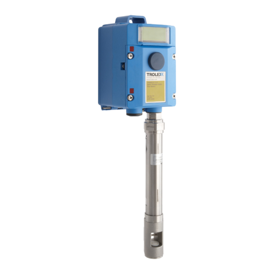
Sentro Vortex Wireless air flow sensor with remote mounted TX5952 . . . XX sensor. For use where fitting space is limited or is difficult to access. TX5952-UM-EN-01a www.trolex.com... -
Page 5: Operating Features
Application Fixed point wireless air flow velocity measurement in pipes, ducts and open roadways. Ventilation, cooling systems and process condition monitoring in heavy duty industrial applications and hazardous areas. Output data linearly proportional to air flow velocity. www.trolex.com TX5952-UM-EN-01a... -
Page 6: Product Options
Mining Ex ia General Purpose TX5951.XX.XX.XX.XX TX5952.XX.XX.XX.XX Please specify cable length and non-standard process fittings when ordering. Please specify the probe length when ordering, probes available from 160 mm to 2000 mm insertion length, in 100 mm increments. TX5952-UM-EN-01a www.trolex.com... -
Page 7: Dimensions
TX5952 User Manual Dimensions 1.4.1 Side Projecting Sensor www.trolex.com TX5952-UM-EN-01a... -
Page 8: Remote Mounted Sensor
1.4.2 Remote Mounted Sensor TX5952-UM-EN-01a www.trolex.com... -
Page 9: Technical Information
Impact limits 20 joules (housing) Output Signals • CommTrac wireless proprietary signal • Auxiliary analogue output signal (4 to 20 mA) to drive a local audio visual alarm Alarms Programmable General and High alarm levels with built-in LED indicators www.trolex.com TX5952-UM-EN-01a... -
Page 10: Electrical Details
10 mA - no backlight 10 mA - no backlight 30 mA - with backlight 30 mA - with backlight Supply current 50 mA with 2 alarm signals 50 mA with 2 alarm signals and backlight and backlight Output relays None None TX5952-UM-EN-01a www.trolex.com... -
Page 11: Sentro Module
• The two alarm signals can be set to illuminate built-in flashing LED indicators • Two auxiliary analogue output signals (4 to 20 mA) to drive a local audio visual alarm unit, if required www.trolex.com TX5952-UM-EN-01a... -
Page 12: Certification
Certification Pending TX5952-UM-EN-01a www.trolex.com... - Page 13 TX5952 User Manual Certification - continued Pending www.trolex.com TX5952-UM-EN-01a...
-
Page 14: Installation
Metric hexagon key set • Standard electrical test meter Trolex recommends that the Sentro Wireless Gas Detector is positioned a minimum of 6 m (20 ft) and no more than 245 m (800 ft) from a Strata CommTrac C node for the Sentro Wireless Gas Detector to work effectively. - Page 15 12.5° from the axis of flow. Tighten the clamping ring with moderate force. Avoid fitting the sensor at low points in pipework structures to prevent the sensing head from being affected by large accumulations of moisture. www.trolex.com TX5952-UM-EN-01a...
-
Page 16: Fitting In Roadways And Tunnels
200 The version with a side projecting sensor can be mounted on to a suitable support using the mounting holes. Alternatively use a standard mounting bush or flange for fitting to a suitable bracket. TX5952-UM-EN-01a www.trolex.com... -
Page 17: Connections
5. 0 V Battery - V (no user connection) 6. Reserved for future use (no user connection) The terminals are located behind the front cover. Use a cross head screwdriver to remove the four screws securing the front cover and move it out of the way. www.trolex.com TX5952-UM-EN-01a... -
Page 18: Setup And Calibration
Setup and Calibration 4.1 Controls and Indicators TX5952-UM-EN-01a www.trolex.com... - Page 19 TX5952 User Manual www.trolex.com TX5952-UM-EN-01a...
-
Page 20: Software Menus
4.2 Software Menus TX5952-UM-EN-01a www.trolex.com... -
Page 21: Navigation
The Sentro Vortex Wireless is factory configured with the Security Code unset. If a Security Code has been subsequently set it will need to be successfully entered before the menus can be accessed, see Section 4.5.1.4 for details. www.trolex.com TX5952-UM-EN-01a... -
Page 22: Power-Up
When the Sentro Vortex Wireless is powered-up the Start-up Screen will appear. The Start-up Screen displays basic information about the system including the software version, driver version and output type. Power On After five seconds the Main Display will appear. The Main Display displays the current airflow. TX5952-UM-EN-01a www.trolex.com... -
Page 23: Main Menu
You can safely remove the front cover of the Sentro Vortex Wireless for setup in a hazardous area, even with the power applied. Checkpoint The Sentro Vortex Wireless will automatically return to the Main Display if no keys are pressed within 30 seconds. www.trolex.com TX5952-UM-EN-01a... -
Page 24: Sentro Setup
This displays basic information about the system including the main software version, system date, system time, driver versions and output formats. From the Sentro Setup Menu press L, navigate to the System Information and press R to display the System Information. TX5952-UM-EN-01a www.trolex.com... - Page 25 From the Set Backlight Menu press R to set the Backlight Illumination to On or Off as required. Press L to move to Save or Cancel as required. Press R to confirm the selection and return to the Display Setup Menu. Adjust Contrast www.trolex.com TX5952-UM-EN-01a...
- Page 26 This enables you to carry-out the setup of the Alerts. From the Sentro Setup Menu press L, navigate to Alert Setup and press R to enter the Alert Setup Menu. The available menus are as follows: • Visual Alert • Confidence Alarm • Exit TX5952-UM-EN-01a www.trolex.com...
- Page 27 From the Confidence Alarm Menu press R to set the Confidence Alert to On or Off as required. Press L to move to Save or Cancel as required. Press R to confirm the selection and return to the Alert Setup Menu. www.trolex.com TX5952-UM-EN-01a...
- Page 28 Save or Cancel as required and Press R to confirm the selection. 4.5.1.5 Exit From the Sentro Setup Menu press L, navigate to Exit, press R to confirm the selection and return to the Main Menu. TX5952-UM-EN-01a www.trolex.com...
-
Page 29: Output Setup
From the Output Setup Menu press L, navigate to Modbus Address and press R to enter the Modbus Address Menu. Press L to navigate to Increase or Decrease as required. Press R to Increase or Decrease the Modbus Address as required. www.trolex.com TX5952-UM-EN-01a... - Page 30 The TxOn Delay and TxOff Delay can be set between 0 and 99 ms. From the Output Setup Menu press L, navigate to TxOn Delay or TxOff Delay as required and Press R to enter the TxOn Delay or TxOff Delay Menu as required. TX5952-UM-EN-01a www.trolex.com...
-
Page 31: Module Setup
Sentro Vortex Wireless. From the Main Menu press L, navigate to Module Setup and press R to enter the Module Setup Menu. The available menus are as follows: • Scaling • Setpoint 1 • Setpoint 2 • Configuration • Exit www.trolex.com TX5952-UM-EN-01a... - Page 32 This can be used to eliminate digit flicker and redundant decimal places. From the Scaling Setup Menu press L, navigate to Sig. Figures and press R to enter the Significant Figures Menu. TX5952-UM-EN-01a www.trolex.com...
- Page 33 Press L to move to the first digit, press R to increment the digit and press L to move to the next digit. Press L and select Save or Cancel as required. Press R to confirm the selection and return to the Scaling Setup Menu. www.trolex.com TX5952-UM-EN-01a...
- Page 34 Units Menu. Press R to change the displayed Units to the preferred Units to be displayed. Press L and select Save or Cancel as required. Press R to confirm the selection and return to the Scaling Setup Menu. TX5952-UM-EN-01a www.trolex.com...
- Page 35 Press R to confirm the selection and return to the Scale Factor Setup Menu. Exit From the Scaling Setup Menu press L, navigate to Exit and press R to Exit the Scaling Setup Menu and return to the Module Setup Menu. www.trolex.com TX5952-UM-EN-01a...
- Page 36 • Exit Activation The Activation mode of Setpoint 1 and Setpoint 2 can be configured to Over or Under as required. From the Setpoint 1 or Setpoint 2 Setup Menu press L, navigate to Activation and press R. TX5952-UM-EN-01a www.trolex.com...
- Page 37 Setpoint 1 or Setpoint 2 Setup Menu. Exit From the Setpoint 1 or Setpoint 2 Setup Menu press L, navigate to Exit, press R to confirm the selection and return to the Module Setup Menu. www.trolex.com TX5952-UM-EN-01a...
- Page 38 From the Set Duty Text Menu press R to increment a character as required and press L to move to the next character. Checkpoint The characters are in the sequence A to Z, 0 to 9 and a Blank Space. TX5952-UM-EN-01a www.trolex.com...
- Page 39 This is particularly useful in electrically noisy environments. From the Configuration Setup Menu press L, navigate to Set Update and press R to enter the Set Update Menu. www.trolex.com TX5952-UM-EN-01a...
- Page 40 L and navigate to Exit. Press R to confirm the selection and return to the Module Setup Menu. 4.5.3.4 Exit From the Module Setup Menu press L, navigate to Exit and press R to confirm the selection and return to the Main Menu. TX5952-UM-EN-01a www.trolex.com...
-
Page 41: Commtrac
This displays the Node ID of the Sentro Vortex Wireless sensor on the CommTrac wireless network. It also displays the Number of Received Comm Node which is the number of nodes that the Sentro Vortex Wireless can see on the CommTrac wireless network. www.trolex.com TX5952-UM-EN-01a... - Page 42 CommTrac wireless node on. The range displayed will be 868 to 925 MHz. Checkpoint This parameter is configured during manufacture. It is user configurable, but Trolex strongly recommends that users DO NOT alter the configured frequency. TX5952-UM-EN-01a www.trolex.com...
- Page 43 This displays the configuration and status of I/O #1 and I/O #2 of the CommTrac wireless module fitted to the Sentro Wireless. The configuration is on of the following: • Alarming • Non Alarming • Confidence Alert • Visual Alarm • Sounder Alarm www.trolex.com TX5952-UM-EN-01a...
- Page 44 CommTrac sensor message when there are no alarms. If there are alarms a sensor message is generated as soon as the I/O board sees them via polling of the Sentro Wireless. The default value for this TX5952-UM-EN-01a www.trolex.com...
- Page 45 Mute Alarm and press R to enter the Mute Alarm Menu. This will clear any I/Os that are set as Alarming I/Os until another event re-sets that Alarming I/O Press R to change the configuration between Alarm Muted and Alarm Not Muted as required. www.trolex.com TX5952-UM-EN-01a...
-
Page 46: Exit
Exit and press R to confirm the selection and return to the Main Display. 4.6 Support If you need technical support to operate this product, or would like details of our after sales technical support packages, please contact your local Trolex service agent or service@trolex.com. TX5952-UM-EN-01a www.trolex.com... -
Page 47: Operation
In the normal mode of operation the Sentro Vortex Wireless will display the air flow rate on the LCD screen in the preferred Units of measurement, this is the Main Display. If the Confidence Alert has been enabled it will flash every 15 seconds. www.trolex.com TX5952-UM-EN-01a... -
Page 48: Diagnostics And Maintenance
Sentro Vortex Wireless an error message will be shown. Module Not Fitted If the sensing module has been removed from the Sentro Vortex Wireless and is out for more than 10 seconds, an error message will be shown. TX5952-UM-EN-01a www.trolex.com... -
Page 49: Maintenance
6.2 Maintenance 6.2.1 Introduction To keep your Sentro Vortex Wireless in the best possible condition and minimise downtime, Trolex strongly recommends that you carry out regular planned preventative maintenance and keep records of the maintenance carried out. The planned preventative maintenance... -
Page 50: Sentro Vortex Wireless - Check
4. If any part of the Sentro Vortex Wireless shows any signs of damage, deformation or missing parts, contact your local Trolex service agent or service@trolex.com for advice on repair or replacement. 5. After the completion of all maintenance, update the maintenance records. -
Page 51: Sentro Vortex Wireless Sensing Probe - Clean
2. Clean the sensing head with a soft brush or cloth if necessary. Checkpoint Do not use sharp tools as this may cause damage to the ultrasound transducers and the transverse strut. 3. After the completion of all maintenance, update the maintenance records. www.trolex.com TX5952-UM-EN-01a... -
Page 52: Sentro Vortex Wireless
3. After the completion of all maintenance, update the maintenance records. 6.3 Disposal Part of the ethos of Trolex is sustainable design. Sentro Vortex Wireless contains materials that can be recovered, recycled and reused. At the end of its useful life ensure that... -
Page 53: Maintenance Records
Sentro Vortex Wireless is located. Checkpoint Consult your local Trolex service agent or the Trolex Product Support Department if you require assistance with disposal: service@trolex.com 6.4 Maintenance Records... -
Page 54: Maintenance And Calibration Log
6.5 Maintenance and Calibration Log Order Reference: TX5952 Serial Number: Date Purchased: Location: Flow Rate: Scheduled Return to Date Fault Recalibrate Comments Check Trolex TX5952-UM-EN-01a www.trolex.com... -
Page 55: Disclaimers
When devices are used for applications with technical safety requirements, the relevant instructions must be followed. Trademarks © 2015 Trolex® Limited. Trolex is a registered trademark of Trolex Limited. The use of all trademarks in this document is acknowledged. Document History Issue 01...
Need help?
Do you have a question about the Sentro Vortex Wireless TX5952 and is the answer not in the manual?
Questions and answers