Table of Contents
Advertisement
Quick Links
Advertisement
Table of Contents

Related Manuals for Emotron DCM

Summary of Contents for Emotron DCM
- Page 1 Emotron DCM Control Unit Instruction manual English...
-
Page 3: Table Of Contents
Start conditions and pause time adjustment ........30 Returning to the default settings............31 Dual-Pump System Installation..........33 Dual-pump system connection ............... 34 Detailed setup for dual-pump system (always use two Emotron DCMs)..................36 Returning to the default settings............38 CG Drives & Automation 01-5965-01r1... - Page 4 Protection and Alarm............... 39 Phase sequence (F1) ................39 Phase asymmetry (F2) ................39 Checking the current (F3) ................ 40 Operating fault (F4) .................. 40 Temperature input (F5)................40 Undervoltage (LU)/Overvoltage (OU) alarm ..........41 Troubleshooting ............... 43 Technical Data ................. 45 10.1 EU (European Union) specifications............
-
Page 5: Inside The Box
Please check the delivery. Despite the fact that all products from CG Drives & Automation are carefully inspected and packed, transport damage may occur: • Your shipment should contain the Emotron DCM, a current transformer, 2x terminal covers (option*) and this instruction manual. - Page 6 Inside the Box CG Drives & Automation 01-5965-01r1...
-
Page 7: Safety
• Pay special attention to the information in this chapter and the parts marked WARNING and CAUTION in the chapter on operation. • Check that the Emotron DCM and the equipment are correctly connected before being taken into use. • Should questions or uncertainties arise, please contact your local sales outlet or see Chapter 12 page 57, Service. - Page 8 Safety CG Drives & Automation 01-5965-01r1...
-
Page 9: Introduction
This instruction manual contains complete instructions for the installation and use of the Emotron DCM. Please read the entire manual before installing or using the DCM. Pay special attention to the Safety chapter in this manual and the parts marked WARNING and CAUTION. - Page 10 The Emotron DCM always stops the pump as soon as it starts to snore (draw air) and restarts it after a calculated pause time or in response to a high-level switch-over. The Emotron DCM is able to check: • Phase sequence.
-
Page 11: Getting Started
Table 1, on page13 and Table 2, on page15 in this manual. Connection and setup before start 1. Connect the Emotron DCM according to Chapters 5 and 6 and Fig. 13 (alternatively, for dual-pumps, Chapter 7 and Fig. 15 and 16). - Page 12 Fig. 1 Pump operation If the Emotron DCM has been used previously, some parameters may have been changed. In such a case, go to Chapter 6 and perform a complete setup for single-pump system installation (alternatively, Chapter 7 for dual-pump system installation).
-
Page 13: Auto Set Performed At Normal Pumping - Pumping Water
1. Check that the amount of water is sufficient for pumping about 30 seconds without snoring. 2. Switch on the supply voltage to the Emotron DCM and set any pump system control equipment to the on position, “1” or Auto. The pump should now be pumping water without snoring. -
Page 14: Auto Set Performed At Snoring - Pumping A Mix Of Air And Water
“SEt” is shown on the display. The stop level is now set, thus stopping the pump when snoring. The stop function is now initiated and the Emotron DCM controls the pump. Adjustments can be made according to Section 6.2, page 30. See also Sections 6.3 and 6.4. -
Page 15: Quick Setup - Flow Chart
Quick setup - flow chart Place the pump in the pit and switch the power on. Assuming all settings are in default Check the troubleshooting Does window procedure, see 00 indicate Chapter 9. an alarm? Press the button Press the AUTO AUTO button for 3... - Page 16 Place both pumps in the pit and switch the power on. Both pumps will start running now . Set the Emotron MASTER DCM window 71 to 2, see Table 8. Set the Emotron SLAVE DCM window 71 to 3. Continue from here with the Quick Setup for Single Pump on the MASTER, see Fig.
-
Page 17: Installation
Before installing, make sure that no voltage is applied to the equipment and that the voltage rating of the Emotron DCM, as shown on the rating plate on the side of the unit, corresponds to the motor/line voltage. - Page 18 NOTE: The current transformer must be linked to the phase connected to terminal 9 (L1). CTM025 2 windings S1 S2 Fig. 6 Example: CTM 025 with 2 windings for a 12 A pump motor Fig. 7 Example: 1, 2 and 3 windings, see also note on page 14 Installation CG Drives &...
- Page 19 NOTE: The current transformer must be linked to the phase connected to terminal 9 (L1). In order to ensure accurate calibration of the Emotron DCM, it is essential that you use the correct CTM (and, additionally, a standard current transformer) and apply the exact number of wirings in accordance with the tables above.
- Page 20 CTM010 2 windings 1 winding 500:5 S1 S2 Fig. 8 Example of a CTM 010 with 2 windings and a primary transformer 500:5 with 1 winding for a 260 A pump motor. See also note on page 15 NOTE: The current transformer(s) must be used according to Table 1 or Table 2.
-
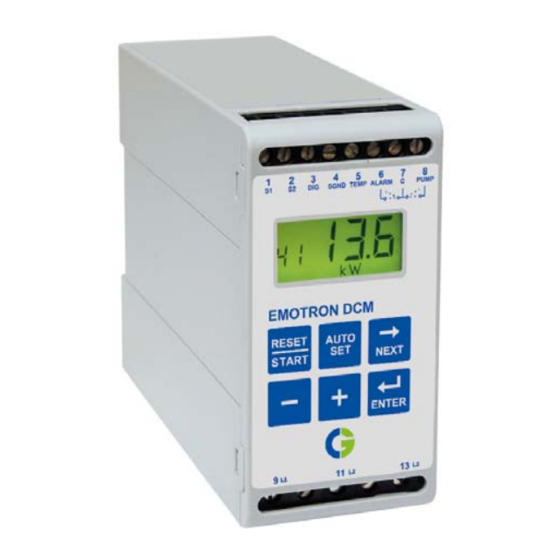
Page 21: The Operator's Panel
2 seconds and then the value 12345 is displayed for 2 seconds. Fig. 9 The display • When the Emotron DCM is turned on, a self test is performed for 3 seconds and all characters and symbols on the display are shown. • During an alarm the entire display flashes. - Page 22 Table 3 Symbols on the LCD display Symbol Meaning Flashing when alarm triggered. Indicates when the value is a time. Parameter settings are locked. Volt Milliampere Minutes Seconds Percent Table 4 Function of the keys Function RESET/START Resets a latched alarm/Starts the pump motor. The stop level is automatically set when the button is pressed Auto set for 3 s.
-
Page 23: Description Of Functions
One minute after any front panel button is pressed, the Emotron DCM returns • Window 00 if an alarm has been triggered. • Window 01 if the pump is paused. When the DCM is SLAVE it displays _ _ _. - Page 24 Fig. 10 Menu structure of the Emotron DCM (see also Table 8, page 53.). The windows 21, 22, 72 and 73 are not shown when the DCM is a SLAVE (dual-pump system). NOTE: The Emotron DCM is designed to work with a pit volume which is ≥...
- Page 25 Example 1 The volume in the pit at pump start after pause Inflow 300 litr es/min time is equal to pump Pump capacity 600 litres/min capacity (litres/min) Window 21 is set to 1 multiplied by level setting (window 21). Examples 1 and 2: Pump capacity 600 (litres/min) x 1 (Value in window 21) =...
- Page 26 NOTE: See note on page 20. Power Time When there is liquid in the pit A1=Motor load when the pump does not snore (window 13 is set to (¯)). A2=Stop level if Auto set is pressed when the pump does not snore (window 11). A3=Snore margin (window 12).
-
Page 27: Connection Terminals
Connection terminals There are 13 connection terminals on the front panel of the Emotron DCM. Table 5 Labelling and functions of connection terminals. Terminal Label Function Current transformer input (CTM xxx), blue wire. Current transformer input (CTM xxx), brown wire. - Page 28 Installation CG Drives & Automation 01-5965-01r1...
-
Page 29: Single-Pump System Installation
Single-Pump System Installation CAUTION! Before carrying out any work, check that any automatic control equipment, etc., is disconnected from the power supply and cannot become live. Exceeding 100 Amps Number of primary and secondary windings see Table 2 CTM 010 Standard transformer Max. -
Page 30: Single-Pump System Connection
9 (L1), 11 (L2), and 13 (L3). Make the connection ahead of the contactor of the motor, to ensure that the DCM also receives power when the motor is not in use. When motor fuses larger than 10 A are used, the DCM (power consumption 6 VA) must be fused independently, see Fig. - Page 31 6.1.4 Operation relay connection (PUMP & C) Terminals 7 and 8 are the operating relay connections that control the start and stop equipment for the pump motor. Terminal 8 (PUMP) is an operating relay output. Terminal 7 (C) is the common input for the operating relay, see Fig.
-
Page 32: Detailed Setup For Single-Pump System
1 to 13, disconnect the wire on terminal 8. Setting up of the Emotron DCM The steps below illustrate examples of how to program the DCM. When the power is turned on, press to proceed to the next window, press... - Page 33 8. In window 32 if window 31 is set to (on), choose temperature alarm latched (on) or temperature alarm not latched (OFF). See section 8.5. 9. In window 41 the permitted phase asymmetry is set between 5% and 50%. Phase asymmetry monitoring is turned off by pressing -, when the window shows 5%.
-
Page 34: Adjustment Of Stop Level
Pit volume window 21=4.8 window 21=2.0 window 21=1.0 Time [min Pausing Pumping Fig. 14 Relative volume in the pit at pump start Adjustment of stop level The stop level can always be adjusted in the following way: 1. Change the snore margin (window 12) and perform a new Auto set. The new stop level will be set in relation to the snore margin. -
Page 35: Returning To The Default Settings
pause time (window 22). The parameters can be adjusted to achieve desired magnitudes of pause times, start level and number of starts per hour. See Fig. 11, page 23, and 14, page 30. The level setting in window 21 is set for shorter or longer pumping and pause cycles. - Page 36 Single-Pump System Installation CG Drives & Automation 01-5965-01r1...
-
Page 37: Dual-Pump System Installation
NOTE: Some useful hints and examples are given in Chapter 6, page 27, Single-Pump System Installation. NOTE: The dual-pump DCM system must not be installed in a pit of extremely small diameter or width. This will result from time to time in the DCMs failing to detect the stop/minimum level. -
Page 38: Dual-Pump System Connection
(Parallel connection of two Emotron DCMs) 7.1.1 Dual-pump supply connection (L1, L2 & L3) Connect the main voltage from each pump to the respective DCM as described in Section 6.1.1, page 28. See Fig. 16. 7.1.2 Dual-pump current transformer connection (S1 &... - Page 39 Connect terminal 3 (DIG) on the DCM MASTER to terminal 3 (DIG) on the DCM SLAVE. Connect terminal 4 (SGND) on the DCM MASTER to ter- minal 4 (SGND) on the DCM SLAVE. See Fig. 16 and Table 8, page 53, win- dow 53.
-
Page 40: Detailed Setup For Dual-Pump System (Always Use Two Emotron Dcms)
1. In window 71 set the required function: dual-pump control MASTER (2) for one of the DCMs and for the other DCM dual-pump control SLAVE (3). The DCM MASTER must be the DCM that is wired for MASTER, see Fig. 16, page 34. - Page 41 (on) or phase asymmetry alarm not latched (OFF) See Section 8.2. 12. In window 51 on the SLAVE DCM, set the alarm relay contact function to NO (normally open) or NC (normally closed), see Section 7.1.3, page 35.
-
Page 42: Returning To The Default Settings
17. Change the level setting in window 21 on the MASTER DCM between 1 - 10 for shorter or longer pump cycles and level in the pit. A low value gives shorter pump cycles and lower level in the pit, see Fig. 11, page 23 and 14, page 32. -
Page 43: Protection And Alarm
Table 6, page 41. Alarm in a dual-pump application The fault code is shown in window 00 of the respective DCM, the alarm relay is only set on terminal 6 of the DCM SLAVE when an error occurs. If a latched alarm occurs it must be reset on the respective DCM by pressing the button or, if specified as digital input, by an external reset. -
Page 44: Checking The Current (F3)
16, page 36 and Section 7.1.4, page 37. Temperature input (F5) Temperature monitoring on pump motor The Emotron DCM can use either an input thermistor (PTC) signal or thermo contact (terminal 5). To activate temperature monitoring, set window 31 to “on”. -
Page 45: Undervoltage (Lu)/Overvoltage (Ou) Alarm
(overvoltage) alarm is generated and the ALARM relay is activated. The pump will not start. Switch the power off. Check that the line voltage corresponds to the voltage range of the DCM according to the rating plate on the side of the unit. - Page 46 Protection and Alarm CG Drives & Automation 01-5965-01r1...
-
Page 47: Troubleshooting
LU Undervoltage or OU Overvoltage alarm, see Section Window 00 shows LU/ 8.6, page 43. Check that the line voltage corresponds to the voltage range of the Emotron DCM according to the rating plate on the side of the unit. WARNING! Switch off the main supply before any wires, etc., are disconnected... - Page 48 The power is represented as a value between 0-125% Power range of the “DCM’s power range”. The DCM is designed to work with a pit volume which is the capacity of the pump (in litres), see Note on Overflowing pit page 22.
-
Page 49: Technical Data
Technical Data 45 mm (1.77’‘) 115 mm (4.53 ) ’‘ Fig. 17 DCM dimensions Table 7 Technical data Dimension (WxHxD) 45 x 90 x 115 mm (1.77" x 3.54" x 4.53") Mounting 35 mm DIN rail 46277 Weight 0.3 kg (10.5 oz) 3 x 100 to 240, 3 x 380 to 500, 3 x 525 to 690 (±10%) - Page 50 Table 7 Technical data Stop delay 1 to 90 s For closing contact. Internal supply 15 - 30 VDC, short- Digital input terminal 3 circuit current 10 - 20 mA Temperature input Internal supply 15-30 VDC, short-circuit current 2 mA - terminal 5 2.5 mA Relay output...
- Page 51 Order number Order number Designation 01-2110-25 Emotron DCM 3x100-240 VAC 01-2110-45 Emotron DCM 3x380-500 VAC 01-2110-55 Emotron DCM 3x525-690 VAC Technical data for current transformer (CT) Type Dimensions (WxØ) Weight* Mounting CTM 010 27 (35) x Ø48 mm 0.20 kg...
-
Page 52: 10.1 Eu (European Union) Specifications
Accessories and documentation Order number Designation 01-2471-10 Current Transformer (CT) CTM010, max. 10 A 01-2471-20 Current Transformer (CT) CTM025, max. 25 A 01-2471-30 Current Transformer (CT) CTM050, max. 50 A 01-2471-40 Current Transformer (CT) CTM100, max. 100 A 01-2368-00 Front Panel Kit 1 (2x terminal covers included) 01-4136-01 2x Terminal covers 01-5965-00... -
Page 53: 10.2 Us Specifications
10.2 US specifications FCC (Federal Communications Commission) This equipment has been tested and found to comply with the limits for a class A digital device pursuant to Part 15 of the FCC Rules. These limits are designed to provide reasonable protection against harmful interference when the equip- ment is operated in a commercial environment. - Page 54 Technical Data CG Drives & Automation 01-5965-01r1...
-
Page 55: Window Parameters
43. Symbol flashing. Remaining time to next pump start. Standard window during pause. When the DCM is 720 - 15 SLAVE - - - appears. min. 900 to 0 s Symbol flashing and m (min) or s (second). - Page 56 Default Master Slave Measured line voltage. 0 to 999 V Symbol V. Measured peak power as percentage of the DCM measurement range. Press - and + (in this window) 0 to 125% simultaneously for 3 seconds to reset the value.
- Page 57 Fig. 11, page 23 and Fig. 14, page 32. See also note on 1.0 to 10.0 page 22. NOTE! The window is not shown when the DCM is SLAVE. Maximum pause time. 0 to 900 s NOTE! The window is not...
- Page 58 1, 2, 3 2 Dual-pump system MASTER 3 Dual-pump system SLAVE. Pump alternating: (on) Alternate by each pump cycle (OFF) The SLAVE DCM only starts when the DCM on/OFF MASTER indicates a fault code. NOTE! The window is not shown when the DCM is SLAVE.
- Page 59 Master Slave Pump starts on high-level switch. (on) Both pumps start. (OFF) one pump starts. on/OFF NOTE! Window is not shown when the DCM is SLAVE. Default settings (dEF). User dEF/USr adjustments mode (USr). CG Drives & Automation 01-5965-01r1 Window Parameters...
- Page 60 Window Parameters CG Drives & Automation 01-5965-01r1...
-
Page 61: Service
Service This manual is valid for the following model: Emotron DCM (as from software version r1d) NOTE: The Emotron DCM does not contain any user-serviceable parts. Breaking the seal over the front panel and housing will invalidate the warranty. Document number:... - Page 62 Service CG Drives & Automation 01-5965-01r1...
-
Page 63: Appendix
Appendix Fig. 18 Single-pump system installation example (Figur 13) CG Drives & Automation 01-5965-01r1 Appendix... - Page 64 Fig. 19 Dual-pump example (Figur 16) Appendix CG Drives & Automation 01-5965-01r1...
- Page 66 CG Drives & Automation Sweden AB Mörsaregatan 12 Box 222 25 SE-250 24 Helsingborg Sweden T +46 42 16 99 00 F +46 42 16 99 49 www.cgglobal.com / www.emotron.com...
Need help?
Do you have a question about the DCM and is the answer not in the manual?
Questions and answers