
Summary of Contents for ADCMT 12707
- Page 1 12707 Resistivity Chamber for Liquid Sample OPERATION MANUAL Manual Number FOE-00000049A00 © 2009 ADC CORPORATION First printing March 31, 2009 All rights reserved. Printed in Japan...
-
Page 3: Table Of Contents
12707 Resistivity Chamber for Liquid Sample Operation Manual Table of Contents 1. Introduction ....................1-1 1.1 Product Overview ......................... 1-1 1.2 Before Using the Product ......................1-2 1.2.1 Appearance and Accessory Check ................. 1-2 1.2.2 Precautions for Transportation and Measurement ............1-3 1.2.3... - Page 4 12707 Resistivity Chamber for Liquid Sample Operation Manual 4. Precautions for Measurement ..............4-1 4.1 Change in Measurement Current ....................4-1 4.2 Discharge and Charge ........................4-3 4.3 Effect of Noise ..........................4-3 4.4 Effect of Vibration ........................4-3 4.5 Securing Insulation ........................4-3 5.
- Page 5 12707 Resistivity Chamber for Liquid Sample Operation Manual List of Illustrations Title Page Operating Environment ................Front Panel ....................Top Panel ...................... Electrode ....................... Internal Electrode Assembly Diagram ............Ring Electrode Assembly Drawing .............. Connecting with the 8340A ................Pouring a Sample ..................
- Page 7 12707 Resistivity Chamber for Liquid Sample Operation Manual List of Tables Title Page Connectable Instruments and Necessary Cables/Adapter ......T-1*...
-
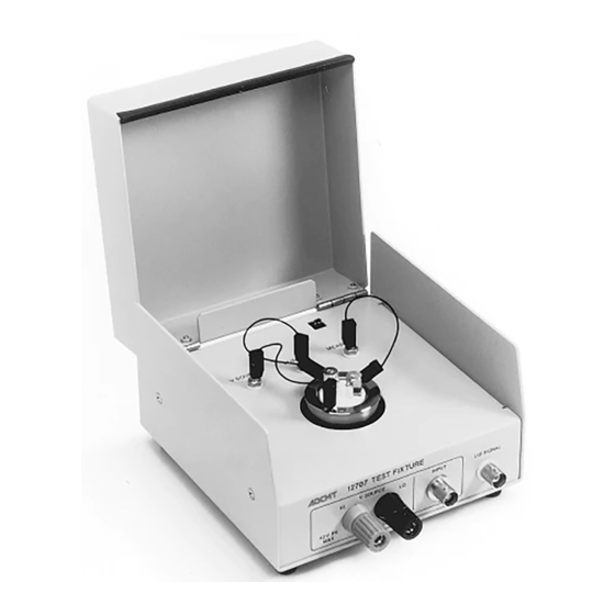
Page 9: Introduction
1. Introduction 1.1 Product Overview The 12707 is a sample box to measure the volume resistivity of a liquid sample such as liquid crystal, consisting of a shield box and electrodes. It is used together with a digital ultra-high resistance/micro current meter such as 8340A or an electrometer such as 8252 or 8240. - Page 10 Ch heck When receivi ing the 1270 7, inspect the e contents of f the package The 12707 co onsists of the e shield box a and the elect trodes. The ring elec ctrode and the e internal ele...
-
Page 11: Before Using The Product
1.2.2 Precautions for Transportation and Measurement (1) Precaution for transportation The internal electrode is not fixed to the shield box. Do not tilt the 12707, otherwise the internal electrode may fall. (2) Precaution for measurement If measurement is performed with the 12707 tilted, a sample will overflow or the internal electrode will not be fully soaked. - Page 12 Manu 1.2 Bef fore Using th he Product 1.2.4 Operating g Environm ment Use the 12707 in an area free fro om dust, corr rosive Avoid using in n a place as b below. gas and v vibrations an...
-
Page 13: Part Names
2707 Resisti ivity Chamb ber for Liqu uid Sample Operation M Manual 2 .1 Pa art Names 2. P Part Nam mes and D Descript tions 2.1 P art Name 2.1.1 Front Pan (1) LID SIG GNAL conne ctor (2) INPUT connector (3) V SOUR RCE termina... -
Page 14: Top Panel (With The Cover Opened)
12707 Resistivity Chamber fo or Liquid Sa ample Oper ration Manu 2 .1 Par rt Names 2.1.2 Top Panel l (with the Cover Ope ened) (8) LID S SIGNAL swit (7) V SO OURCE termin (6) GUAR RD terminal (5) Measu... -
Page 15: Electrodes
2707 Resisti ivity Chamb ber for Liqu uid Sample Operation M Manual 2 .1 Pa art Names 2.1.3 Electrode (16) ) G terminal (15) ) M terminal (11) Internal electrode (13) Guard electrode A (12) Ma ain electrode (14) Guard electrode B (17) V term minal... -
Page 16: Part Descriptions
A terminal to connect with an application voltage source such as the 8340A or 8252. The HI is connected to the V SOURCE terminal (7) on the top panel. CAUTION The maximum voltage of the 12707 is 45 V. Be sure to operate the 12707 at or below the maximum voltage. - Page 17 12707 Resistivity Chamber for Liquid Sample Operation Manual 2 .2 Part Descriptions See Figure 2-2. (4) Electrode insertion opening The electrode is inserted into this opening. The projections in the inside are aligned with the holes on the bottom of the electrode.
- Page 18 12707 Resistivity Chamber for Liquid Sample Operation Manual 2 .2 Part Descriptions See Figure 2-3. (10) Ring electrode A container to put a measurement sample in. Voltage is applied to this electrode. (11) Internal electrode This electrode is used in the ring electrode. It contains the main electrode and the guard electrodes.
-
Page 19: Measurement Method
12707 Resistivity Chamber for Liquid Sample Operation Manual 3. Measurement Method 3. Measurement Method Start Cleaning the electrodes : Refer to Section 3.1. Connecting with a measuring instrument : Refer to Section 3.2. Pouring a sample : Refer to Section 3.3. -
Page 20: Cleaning The Electrodes
12707 Resistivity Chamber for Liquid Sample Operation Manual 3.1 Cleaning the Electrodes 3.1 Cleaning the Electrodes CAUTION To perform precise measurement, clean the electrodes before and after measurement. In insulation resistance measurement, dirt on the electrodes or sample residue may cause measurement errors. - Page 21 2707 Resisti ivity Chamb ber for Liqu uid Sample Operation M Manual 3.1 Cl eaning the E Electrodes ) Main electr rode 2) Guard elect trode B ) Guard elect trode A 4) M terminal ) G terminal 6) Flat head sc crew M3X20 7) Insulator B ) Insulator D...
-
Page 22: Cleaning The Ring Electrode
12707 Resistivity Chamber fo or Liquid Sa ample Oper ration Manu 3.1 Cle eaning the E lectrodes 3.1.2 Cleaning the Ring E Electrode See Figu ure 3-2. Procedure: Turn the e base (2) cou unterclockwi ise to remove e it from the ring electrod de (1). - Page 23 A01009). 2) Connect t the V SOUR RCE HI of th he 8340A to the V SOUR RCE HI of th he 12707 by u using the banana-b banana cable e (A01240). 3) Connect t the LID SIG GNAL of the...
-
Page 24: Connecting To The Measuring Instruments
Connecting with the 8240 Procedure: (1) Connect the INPUT of the 8240 to the INPUT of the 12707 by using the TRIAX-TRIAX cable (A01009). (2) Connect a voltage source to the V SOURCE of the 12707 by using the banana-banana ca- ble (A01240). -
Page 25: Connecting With The 8252
(1) Connect the INPUT of the 8252 to the INPUT of the 12707 by using the TRIAX-TRIAX cable (A01009). (2) Connect the V SOURCE of the 8252 to the V SOURCE of the 12707 by using the output cable (A01044) and the banana adapter (A08531). -
Page 26: Pouring A Sample
12707 Resistivity Chamber fo or Liquid Sa ample Oper ration Manu 3.3 Pou uring a Samp 3.3 P ouring a Sample Procedure: 1) Take out t the internal l electrode, a and pour a sa ample of 0.8 to 1 cc into the ring elec ctrode. -
Page 27: Setting The Electrode
2707 Resisti ivity Chamb ber for Liqu uid Sample Operation M Manual 3.4 S Setting the E Electrode 3.4 S etting the e Electrod Procedure: 1) There ar re two projec ctions in the e electrode in nsertion open ning of the s shield box. -
Page 28: Measurement
12707 Resistivity Chamber for Liquid Sample Operation Manual 3.5 Measurement 3.5 Measurement Perform measurement in accordance with the operation manual of each measuring instrument. In insulation resistance measurement, VSIM (voltage source current measurement) is generally conducted to obtain the resistance value by R=V/I. -
Page 29: Setting The 8252
12707 Resistivity Chamber for Liquid Sample Operation Manual 3.5 Measurement 3.5.3 Setting the 8252. Procedure: (1) Set the function to DCI (DC current measurement). (2) Setting the IM/RM switch to RM will read the resistance value. (3) Set the applied voltage. - Page 30 12707 Resistivity Chamber fo or Liquid Sa ample Oper ration Manu 3.6 Vo lume Resisti ivity Calcula ation 3.6 V Volume Re esistivity C Calculati Multiply the measured va alue by electr rode coeffici ient 147.7 to obtain the v olume resisti ivity.
- Page 31 2707 Resisti ivity Chamb ber for Liqu uid Sample Operation M Manual Volume R Resistivity Ca alculation 3) Electrod de coefficient t setting ess the COEF F key once to o display the electrode co oefficient sett ting screen. ess the numbe er keys [1][4 4][7][.][7] to input the ele...
- Page 33 2707 Resisti ivity Chamb ber for Liqu uid Sample Operation M Manual 4.1 C Change in M Measurement t Current 4. P Precautio ons for M Measurem ment 4.1 C Change in Measure ement Cur rrent 1) Measure ement Circui The insu ulation resis tance value...
- Page 34 12707 Resistivity Chamber fo or Liquid Sa ample Oper ration Manu 4.1 Ch hange in Mea asurement Cu urrent 2) Measure ement Curren The foll lowing figur re shows cha ange in curr rent after cha anging the s switch S from...
-
Page 35: Discharge And Charge
12707 Resistivity Chamber for Liquid Sample Operation Manual 4.2 Discharge and Charge 4.2 Discharge and Charge (1) Discharge Insulation resistance measurement supposes that the surface or inside of the sample is not charged. However, in fact, charge generation inevitably occurs by friction during trans- portation or repeated measurement. -
Page 37: Specifications
12707 Resistivity Chamber for Liquid Sample Operation Manual 5. Specifications 5. Specifications Electrode coefficient 147.7 Electrode material Metal part: brass (nickel plating) Insulating material: Teflon Insulation resistance Temperature: 23±5°C, relative humidity: 70% or less, 60 V DC Ω or higher Main electrode –... -
Page 39: Measurement Principle
2707 Resisti ivity Chamb ber for Liqu uid Sample Operation M Manual A.1 V Volume Resi stivity Meas surement Pr rinciple and Calculation n Method A.1 V Volume Re esistivity M Measurem ment Prin nciple and d Calculat tion Meth 1) Measurem ment principl S: Are... - Page 40 12707 Resistivity Chamber fo or Liquid Sa ample Oper ration Manu A.1 Vo olume Resisti ivity Measur rement Princ ciple and Cal culation Met thod 2) Calculatio on Method pposed electr rode Main e electrode Figure A-2 Electrode C Coefficient C...
-
Page 41: Internal Connection
2707 Resisti ivity Chamb ber for Liqu uid Sample Operation M Manual Internal Co onnection A.2 In n ternal C onnection Figure e A-3 Intern nal Connecti...
Need help?
Do you have a question about the 12707 and is the answer not in the manual?
Questions and answers