Table of Contents
Advertisement
Quick Links
HUIZHOU EPEVER TECHNOLOGY CO., LTD.
※ Thanks for selecting the EPEVER-RTU-4G-C GPRS transmission
terminal. Please read this manual carefully before using.
※ Please keep this manual for future reference.
USER MANUAL
EPEVER-RTU-4G-C
1 Overview
EPEVER-RTU-4G-C is a new wireless data transmission terminal based on
the 4G network. Through the GSM/GPRS SIM card, the controllers,
inverters, or inverter/chargers connected to the EPEVER-RTU-4G-C can
easily access our company's cloud server. It helps realize remote, wireless,
and networked communication among devices quickly. It is equipped with
complete network coverage, a flexible connection (use immediately after
installation), low operating costs (charge according to the network traffic),
and convenient operations. EPEVER-RTU-4G-C can be widely used in
fields of solar light and emergency backup power, such as road monitoring,
communication
stations,
home
environmental monitoring, and backup power monitoring.
Features:
High-performance Cortex-M0 embedded processor
Built-in watchdog ensures no crash and automatic recovery
Support Unicom and mobile network, universal four frequency bands
Support PC software setting, serial port command, SMS command
Wider input voltage(DC8~64V or DC5V), suitable for various
applications
Support controller/inverter designed with RS485 communication mode
Data transmitted by the fixed IP or dynamic domain name resolution
Support TCP/UDP protocol
Support PC or phone APP to monitor status and modify parameters
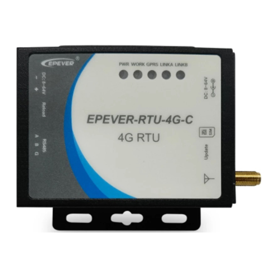
2 Characteristics
❶
❼
LINKB indicator
❷
❽
LINKA indicator
❸
❾
GPRS indicator
❹
❿
WORK indicator
solar
stations,
meteorological
(1)
RS485 terminals
Antenna connector
Upgrade port
SIM card(china Unicom/Mobile) slot
1
Tel:+86-10-82894896/82894112/+86-752-3889706
❺
Power indicator
❻
DC power terminals
(1) Terminal Definition
DC power
❻
terminals
RS485
❼
terminals
(2) Press the yellow button ⓬, and the SIM card slot is pushed out.
3 Auxiliary Accessory
Type
Picture
Included
Optional
(1) Pin definition
Model
and
GND
A
B
4 Indicator instruction
Indicator
LINKB
LINKA
GPRS
WORK
POWER
5 System connection
Wiring sequence
① Communication Part: Connect the SIM card, antenna, and
communication cables.
② Power Part: Power on the EPEVER-RTU-4G-C by connecting a
battery.
Website:www.epever.com
⓫
DC power connector
⓬
SIM card slot push-out button
8~64V or 5V
GND
VCC
5.08-2 2P
1
2
RS485
A
B
G
5.08-3 2P
1
2
3
Name
Connect to the
antenna connector❽
Antenna
for data sending or
receiving.
RJ45 to 5.08
Connect to the
cable(CC-RJ45-5.0
RS485 terminals❼
(1)
8-150U)
for data transmission.
Suitable for
3.81 to 5.08
iTracer-AD/iTracer-N
cable(CC-3.81-5.08
D/eTracer-BND/eTra
(1)
-100U)
cer-AD.
CC-RJ45-5.08-150U
CC-3.81-5.08-100U
Black
Blue
Green
Status
On Solid
Connect to Socket B
On Solid
Connect to Socket A
On Solid
Connect to GPRS
Flashing
Working indicator
On Solid(Red)
2
1-GND
2-VCC
1-A
2-B
3-GND
Function
Black
Green
Red
Instruction
Power on
Advertisement
Table of Contents

Summary of Contents for Epever EPEVER-RTU-4G-C
- Page 1 Antenna for data sending or 1 Overview receiving. Included EPEVER-RTU-4G-C is a new wireless data transmission terminal based on RJ45 to 5.08 Connect to the the 4G network. Through the GSM/GPRS SIM card, the controllers, cable(CC-RJ45-5.0 RS485 terminals❼...
- Page 2 The male head standard in "Communication to the EPEVER-RTU-4G-C. standard Interface Standard V-1.1" 2) The EPEVER-RTU-4G-C transmits the received data to the cloud server 9600Bps~115200bps, 8N1 Baud for recording and processing via the 4G and Internet network. 50Ω SMA (female head)
Need help?
Do you have a question about the EPEVER-RTU-4G-C and is the answer not in the manual?
Questions and answers