Table of Contents
Advertisement
Quick Links
Advertisement
Table of Contents

Related Manuals for HikRobot VB2200 Series

Summary of Contents for HikRobot VB2200 Series
- Page 1 VB2200 Series Vision Box User Manual...
- Page 2 WITHOUT LIMITATION, MERCHANTABILITY, SATISFACTORY QUALITY, OR FITNESS FOR A PARTICULAR PURPOSE. THE USE OF THE PRODUCT BY YOU IS AT YOUR OWN RISK. IN NO EVENT WILL HIKROBOT BE LIABLE TO YOU FOR ANY SPECIAL, CONSEQUENTIAL, INCIDENTAL, OR INDIRECT DAMAGES,...
- Page 3 TO ANY NUCLEAR EXPLOSIVE OR UNSAFE NUCLEAR FUEL-CYCLE, OR IN SUPPORT OF HUMAN RIGHTS ABUSES. THE PERFORMANCE DATA IN THIS PUBLICATION IS BASED ON HIKROBOT'S INTERNAL RESEARCH/EVALUATION. ACTUAL DATA MAY VARY DEPENDING ON SPECIFIC CONFIGURATIONS AND OPERATING CONDITIONS AND HIKROBOT SHALL NOT BEAR THE CONSEQUENCES ARISING THEREFROM.
- Page 4 Indicates a hazard with a high level of risk, which if not avoided, will result in death or serious injury. Available Model This manual is applicable to the VB2200 Series Vision Box. Safety Instructions These instructions are intended to ensure that the user can use the product correctly to avoid danger or property loss.
- Page 5 VB2200 Series Vision Box User Manual · Avoid contact with exposed circuit. When the device is powered on, avoid contact with exposed junctions and parts. Use the power adapter provided by the regular manufacturer. DO NOT connect multiple devices to one power adapter, to avoid over-heating or fire hazards caused by overload.
- Page 6 VB2200 Series Vision Box User Manual · disassemble or modify the device in any way. (The company does not bear any liability for any problem arising from unauthorized modification or maintenance). Please properly preserve all the original packaging materials of the product so that when problems arise, the product can be packed with packaging materials and sent to the agent or returned to the manufacturer for processing.
-
Page 7: Table Of Contents
VB2200 Series Vision Box User Manual · Table of Contents Chapter 1 Overview ........................1 1.1 Introduction ........................1 1.2 Key Features ........................1 Chapter 2 Installation ......................... 2 2.1 Dimension .......................... 2 2.2 Installation .......................... 2 2.3 Remote Access ........................3 2.4 Accessories ......................... - Page 8 VB2200 Series Vision Box User Manual · Chapter 5 System Reinstallation ....................17 Chapter 6 Trouble Shooting ...................... 18 viii...
-
Page 9: Chapter 1 Overview
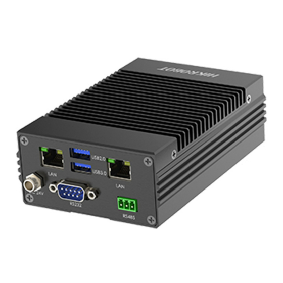
Chapter 1 Overview 1.1 Introduction Designed for the control system, the VB2200 series vision box adopts the Intel® E3845 Quad-core SoC processor and integrates with the various interfaces in the machine vision applications, such as Gigabit Ethernet interface, USB, I/O, etc., featuring stable performance, compact structure, fast response, etc. -
Page 10: Chapter 2 Installation
VB2200 Series Vision Box User Manual · Chapter 2 Installation 2.1 Dimension Refer to the following figure for the dimensions of the vision box. 4-M3 5 42.4 USB2.0 PWR HDMI1 USB2.0 USB3.0 HDMI2 1 2 3 4 G 1 2 3 4 G... -
Page 11: Remote Access
VB2200 Series Vision Box User Manual · 2.3 Remote Access You can operate the device in the monitor after connecting them via HDMI cable. You also can remotely access the device via the PC in the same network segment. IP address can be got by packet capturing tools or others. -
Page 12: Chapter 3 Interface Description
VB2200 Series Vision Box User Manual · Chapter 3 Interface Description 3.1 Interface Description Refer to the following figure for the interfaces on the panel of vision box: USB2.0 HDMI1 USB3.0 USB2.0 HDMI2 1 2 3 4 G 1 2 3 4... -
Page 13: Gpio Interface
VB2200 Series Vision Box User Manual · 3.2 GPIO Interface 3.2.1 Pin Definitions The device IO interface has 11 pins. Refer to the following table for the pin definitions of GPIO inputs and outputs: Table 3-2 Pin Definitions Pin No. - Page 14 VB2200 Series Vision Box User Manual · Table 3-3 Voltage Range of Opto-Isolated Input Electrical Level Input Type Voltage Range High electrical level input 10 V to 30 V Low electrical level input 0 V to 2 V The voltage range of low electrical level Input is set to 0 V to 2 V due to the voltage fluctuation of 0 V voltage under industrial application.
-
Page 15: Opto-Isolated Output
VB2200 Series Vision Box User Manual · You can design circuit diagram for other devices according to the two diagrams above. 3.2.3 Opto-Isolated Output The opto-isolated output of vision box adopts open collector and unidirectional output. When the circuit is used for output, current from external power supply flows into opto-isolated output port, then flows out. -
Page 16: Built-In Usb Interface
VB2200 Series Vision Box User Manual · HDMI1 Device USB2.0 HDMI2 1 2 3 4 G 1 2 3 4 C G 1 2 3 4 G 1 2 3 4 C G GND of VCC LIGHT Power Supply Ground... -
Page 17: Rs-232 Interface
VB2200 Series Vision Box User Manual · 3.4 RS-232 Interface The device provides a standard D-sub 9-pin RS-232 communication interface. Refer to the following table for the pin definitions. 2 3 4 5 7 8 9 Figure 3-7 RS-232 Interface Table 3-5 RS-232 Pin Definitions Pin No. -
Page 18: Hdmi Interface
VB2200 Series Vision Box User Manual · Table 3-6 RS-485 Pin Definitions Pin No. Definitions 485- 485+ RS-485 corresponds to COM3 in the default system. 3.6 HDMI Interface The device provides 2 HDMI interfaces for connecting with the monitor with max. resolution of 2560 ×... -
Page 19: Chapter 4 Io Controller Settings
VB2200 Series Vision Box User Manual · Chapter 4 IO Controller Settings 4.1 IO Controller The vision box’s GPIO and light source interfaces can be controlled via SDK and IO controller. The main interface of the IO controller is shown below. -
Page 20: Communication Port
VB2200 Series Vision Box User Manual · 4.2 Communication Port You can go to Device Manager > Ports (COM & LPT) to view the corresponding relation between serial physical port and COM. Steps: 1. Right click on This PC icon on the desktop, and select Manage from the context menu. -
Page 21: Serial Port Connection Settings
VB2200 Series Vision Box User Manual · COM Port Function COM2 GPIO 0x0000000A (10) COM3 RS-485 0x00000003 (03) COM4 0x0000000B (11) You need to configure COM port settings according to the table above if the device’s system is not a default one. -
Page 22: Input Settings
VB2200 Series Vision Box User Manual · 4.4.2 Input Settings In Input Settings, select Port, set Trigger Signal and Upload Signal according to actual demands. Enter Trigger Delay and Debouncer Time to delay the trigger signal received time, and to filter out unwanted short input signals respectively. -
Page 23: Output Enable
VB2200 Series Vision Box User Manual · Pulse Period and Pulse Width are only valid when you select Multi_Pulse as Mode. The Duration cannot be smaller than the Pulse Period when Multi_Pulse is selected as Mode. 4.5.2 Output Enable Output enable is used to set whether the device outputs signal or not. -
Page 24: View Message
VB2200 Series Vision Box User Manual · 4.8 View Message The message window displays messages in real time. You can clear them or save them in txt file. 4.9 Enable Edge Detection Edge detection allows you to view the input edge signals and its quantity via message window in real time. - Page 25 VB2200 Series Vision Box User Manual · Chapter 5 System Reinstallation The default system of the device is Windows Embedded Standard 7 or Windows 10 loT. If the system exception occurs, or you need to use other systems, and then system reinstallation is required.
- Page 26 VB2200 Series Vision Box User Manual · Chapter 6 Trouble Shooting Table 6-1 Trouble Shooting No. Trouble Solution The device does not have the VGA Order original HDMI-to-VGA cable or purchase suitable cable. interface. 1. Reconnect the HDMI cable, or replace VGA cable.
- Page 27 VB2200 Series Vision Box User Manual · No. Trouble Solution whether the the paramater configurations are completely enabled. 3. Replace the vision box and check whether the IO port is burned out.
- Page 28 UD23619B...
Need help?
Do you have a question about the VB2200 Series and is the answer not in the manual?
Questions and answers