
Summary of Contents for CPAT FLEX DRV3
- Page 1 Portable Digital Leakage Detector User Manual (DRV3) v 1.3 / 2018.01.04 Part No. 100-00001-001...
- Page 2 Fourth edition (v1.3): January 2018 Part No. 100-00001-001 Published by: Ef gis 4101 Molson St., Suite 400 Montreal, Quebec CANADA H1Y 3L1 Telephone: + 1-514-495-0018 Toll-free (North America): + 1-888-495-6577 Fax: + 1-514-495-4191 Copyright © 2018 Ef gis All rights reserved CPAT FLEX (DRV3)
-
Page 3: Table Of Contents
ef gis.com Contents 1. General Information ......5 1.1 About this Manual ........5 1.2 Explanation of Symbols Used . - Page 4 B.2.6 Disclaimer ........38 DRV3 Docking Station Installation ....40 CPAT FLEX (DRV3)
-
Page 5: General Information
ef gis.com 1. General Information 1.1 About this Manual This manual describes the features, operation and setup of the DRV3 digital portable leakage detection meter. You will nd important safety information in this manual. We strongly recommend that all users read this manual. Use of this product other than for its intended application may compromise the unit’s safety features 1.2 Explanation of Symbols Used The following symbols are used in this Manual:... -
Page 6: Technical Support
As well, if your company requires regular calibration of all equipment, or requires a calibration certi cate for the DRV3, a calibration service is available through Ef gis. For more information on calibration services, please contact your Ef gis representative. CPAT FLEX (DRV3) -
Page 7: Ef Gis Website
It functions as a portable dual-band nd-and- x meter and as a monitoring probe when part of the CPAT FLEX system. It is frequency agile from 118 to 140 MHz (Mid band tuner) and from 572 to 960 MHz (LTE band tuner). The DRV3 can easily be set up via its intuitive user interface. - Page 8 Portable antenna 572-960 MHz (SMA connector) 7 150-00032-001 Vehicle docking station 8 150-00031-001 DRV3 9 012-00020-001 Docking station’s Flex post 10 100-00001-001 DRV3 user manual To place an order, please call Ef gis at + 1-888-495-6577 or + 1-514-495-0018 CPAT FLEX (DRV3)
-
Page 9: Drv3 Optional Accessories
(LTE-band tuner) • User-adjustable frequency displayed in 100 Hz steps • 3 favorite frequency presets • Based on Ef gis’s CPAT leakage monitoring system technology NOTE In both bands, leakage detection is based on signal tag recognition to lter noise from real leakage points. This means that monitored frequencies must be tagged in order to detected leakage. -
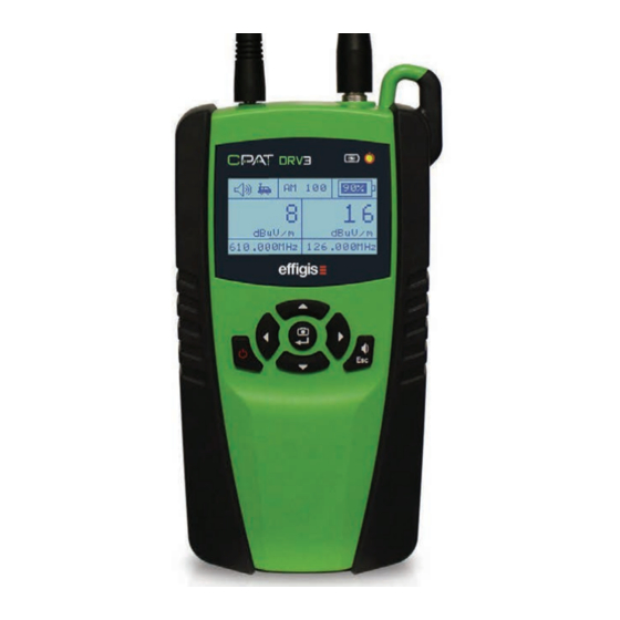
Page 10: Physical Overview
LCD display Navigation arrow Navigation arrow Navigation arrow Snapshot / Enter Esc and Volume / On / Off button Mute toggle Navigation arrow Figure 2: Front view of DRV3 CPAT FLEX (DRV3) -
Page 11: Power And Data Interface
ef gis.com 2.4.3 Power and Data Interface The DRV3 has one round pin interface on the bottom of the unit, used only to connect the AC adapter (supplied by Ef gis) when the docking station is not used. This connection allows you to recharge the battery and power the DRV3. - Page 12 The docking station is available with a exible mounting post that is designed to be installed in a service vehicle. For further details and installation procedures, see section 3.1 Docking Station Installation starting on page 16. CPAT FLEX (DRV3)
-
Page 13: Antenna Connectors
ef gis.com 2.4.5 Antenna Connectors The 2 connectors at the top of the unit are designed for the rubber duck antennas. These antennas are used only when the unit is not docked. Figure 5: Top view of DRV3 As soon as the DRV3 is docked, there is an internal mechanical switch that transfers the RF input readings to the docking station. - Page 14 Figure 6: Rear view of docking station CPAT FLEX (DRV3)
-
Page 15: Speaker
ef gis.com Figure 7: Rooftop antenna connexions NOTE The link with the DRV3’s tuners is made through the two small round connectors on the front of docking station which align with the 2 holes protected by the slider located at the back of the DRV3. The slider automatically opens when docked. -
Page 16: Setup
RF antennas. It typically mounts on a ex post secured to the vehicle’s passenger oor near the 12V power source so the DRV3 can remain in the support bracket while charging. You will require 3 screws (not included) to secure the ex post to the oor. CPAT FLEX (DRV3) - Page 17 ef gis.com Figure 8: Docking station used in service vehicle CAUTION! Do not disconnect or modify any vehicle security systems such as airbags or seatbelts. Security systems wires use yellow sleeves and yellow connectors. Accidental triggering of these systems may cause severe injuries. User Manual...
- Page 18 • Start by rst sliding the bottom of the unit into the station. • Then, gently press the top of the unit until the DRV3 slides under the top clip. You will hear a click when the clip engages. For further details, see the installation diagram on page 40. CPAT FLEX (DRV3)
-
Page 19: Drv3 Parameters
ef gis.com 3.2 DRV3 Parameters When used in autonomous measurement mode (with the optional ARD4 module), all operating parameters are set automatically by the ARD4. NOTE In autonomous measurement mode, access to menus is blocked to prevent any changes to operating parameters. The menus are available as soon as you exit this mode. -
Page 20: Setting Up Antennas
3. Select the type of antenna that is physically connected to the selected antenna interface. The possible values are: • Rubber* Default value • Dipole • Monopole • None** Used by Ef gis service personnel for maintenance/calibration purposes CPAT FLEX (DRV3) -
Page 21: Using Spectrum Mode
DRV3 to be docked in order to operate in this mode. 3.2.3 Using Spectrum Mode Spectrum mode is used for on-the-spot diagnosis by CPAT support team but is also available for normal users. In this mode, the DRV3 can work as a simpli ed spectrum analyzer. -
Page 22: Setting Up Bands
3. Press Enter ( ↵ ) to save the value. The cursor automatically returns to the left column. Continue con guring other parameters if desired. 4. Press Esc to return to measurement mode. 3.2.6 Setting up Sound Reference Volume The DRV3 can emit an audible tone to provide an audio feedback of measurements. The CPAT FLEX (DRV3) - Page 23 ef gis.com volume setting affects the basic reference level for the tone. During normal use, unless the ‘mute’ option is used, the tone increases with the leak’s signal strength. The reference volume of the tone can be set to LOW, MED or HIGH, or the sound can be turned off with the ‘mute’...
-
Page 24: Setting Up Units
Make sure that the frequencies you con gure in the DRV3 match the leakage monitoring pilot signals used by the operator. NOTE Selected frequencies and tagging parameters must match the ones used with the DSG1, installed at the headend, in order to obtain leakage measurements. CPAT FLEX (DRV3) -
Page 25: Using Pressure Test Mode
ef gis.com To edit any preset frequency and select the active monitoring frequency: 1. In the settings menu (page 3), select Frequency. 2. Press the right arrow ( ) to access the band and frequency options. 3. Select the desired band (Mid/Aero or LTE) and then press the right arrow to display the list of preset frequencies (Freq 1, Freq 2, and Freq 3). -
Page 26: Using Channel Tag Detection
You can also adjust the detection threshold of the channel to allow the DRV3 to discriminate between channel noise and the tag signal. The detection threshold setting is at the end of the Tag Cfg menu. Once properly setup, the letter ‘t’ will appear at the bottom of the main measurement mode CPAT FLEX (DRV3) -
Page 27: Setting Up Detection
ef gis.com screen if the DRV3 detects the tag in the monitored frequencies. If the rules governing sound section 3.2.6 are respected, the ‘t’ icon is replaced by a speaker icon. To set up and enable/disable channel tag detection: 1. In the settings menu (page 3), select Tag Cfg. The current detection setting is displayed to the right. -
Page 28: Setting Up The Cw To Qam Delta
1. In the settings menu (page 4), select Backlight. The current setting is displayed to the right. 2. Press the right arrow to move to the options and use the up and down arrows to select the backlight properties from the available options: CPAT FLEX (DRV3) -
Page 29: Setting Up Contrast
ef gis.com Remains on (lit) AUTO 10s Turns off after 10 seconds if no keys are pressed AUTO 30s Turns off after 30 seconds if no keys are pressed AUTO 60s Turns off after 60 seconds if no keys are pressed No backlight 3. -
Page 30: Displaying The Drv3'S Version
To view the device ID, go to the settings menu (page 6). The unit’s ID is displayed to the right. Press Esc until you return to measurement mode, or press the left arrow ( ) to return to the settings menu to con gure or view other parameters. CPAT FLEX (DRV3) -
Page 31: Operation And Maintenance
ef gis.com 4. Operation and Maintenance 4.1 Reading the Measurement Mode Screen The DRV3 starts up in measurement mode by default, and immediately detects and displays levels for the last frequency selected. Unless the DRV3 has been set up for single band detection, it simultaneously monitors the selected frequencies in the Mid band and the LTE band. -
Page 32: Adjusting Volume During Normal Use
200 Hz to about 800 Hz. In measurement mode, you can enable or mute the audio by pressing the volume key labelled Esc. To adjust the reference volume of the audio tone, see section 3.2.5 Setting up Sound on page 22. CPAT FLEX (DRV3) -
Page 33: Using The Snapshot Feature
ef gis.com 4.3 Using the Snapshot Feature During normal operation, you can capture the actual RF level measurement at your leakage monitoring frequency. This feature can help you compare levels you are reading in different locations or at different distances from the leakage source. You can take a snapshot by pressing the key labelled ( ↵... -
Page 34: Updating The Drv3'S Firmware
ARD4, or manually using a computer. When a new rmware update is available, the Ef gis support team will plan update deployment with your CPAT internal manager. To check which versions are currently installed in the DRV3, access the DRV3’s setup mode by pressing the up or down arrow and scroll to the Version menu. -
Page 35: Appendix A - Specifications
ef gis.com Appendix A – Specifications A.1 Technical Detector type Dual-band digital receiver/demodulator Frequency range Agile from 118 to 140 MHz (Mid-band) Agile from 572 to 960 MHz (LTE-band) Channel tuning Con gurable via USB port and by front panel buttons Tuning resolution 100 Hz Level range... -
Page 36: Appendix B - Our Services
Ef gis Support. Ef gis is not liable for any damage that may occur during shipping. The customer should clearly mark the Ef gis’ issued RA or reference number on the outside of the package and ship it prepaid and insured to Ef gis. CPAT FLEX (DRV3) -
Page 37: Limited Product Warranty
ef gis.com Equipment repaired or replaced under warranty will be returned at Ef gis’ expense to Customer (Canada/USA) or Ef gis’ representative (all other countries). All other non-warranty repairs will be returned at Customer’s expense to Customer (Canada/ USA) or Ef gis’ representative (all other countries). B.2 Limited Product Warranty B.2.1 Hardware Ef gis warrants to the original end user (Customer) that the new Ef gis branded products will... -
Page 38: Refurbished Parts And Prior Testing
INCLUDING, BUT NOT LIMITED TO, ANY WARRANTIES OR CONDITIONS OF MERCHANTABILITY, SATISFACTORY QUALITY, FITNESS FOR A PARTICULAR PURPOSE, AND NON-INFRINGEMENT, REGARDLESS OF THE LEGAL THEORY ON WHICH SUCH IMPLIED WARRANTY MAY BE BASED, INCLUDING, WITHOUT LIMITATION, CONTRACT, COURSE OF DEALING, USAGE, OR TRADE PRACTICE. CPAT FLEX (DRV3) - Page 39 ef gis.com User Manual...
-
Page 40: Drv3 Docking Station Installation
Attach docking station Attach the DRV3 docking station to the Flex mount using the 4 pan head Phillips screws (included with the docking station). Adjust docking station orientation and tighten the thumbscrew. Pan head Phillips screw Flex mount post CPAT FLEX (DRV3) - Page 41 USB cable (required only if the DRV3 is used with an ARD4). Secure wires with a cable tie. Connect the DRV3 to ARD4 (optional) Note: See ‘‘CPAT FLEX Operation Manual’’ ARD4 for the ARD4 installation details. USB cable from DRV3 docking station Dock:...
- Page 42 CPAT FLEX (DRV3)
- Page 43 ef gis.com User Manual...
- Page 44 effigis.com 1-888-495-6577 © 2018 Effigis. All rights reserved. 006-000037-105...
Need help?
Do you have a question about the FLEX DRV3 and is the answer not in the manual?
Questions and answers