Advertisement
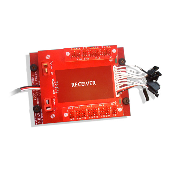
Receiver Connections
The receiver servo outputs are connected to the pigtails with the single white lead
coming out of the PowerExpander. The channels that have four servo outputs have
each servo signal output individually buffered. The channels that have two servo
outputs are not buffered. These leads are arranged to correspond to the output order
of Futaba and JR end-loading receivers. Other receivers can also be accommodated
such as end-loading Multiplex receivers. You may also need to swap an input pigtail
to a different channel on the receiver to match up with a buffered output. The
Pwr/DSC three-wire connector plugs into the receiver's battery input. If you are
using a receiver that shares a servo output with the battery input then you can make
an adapter (female-to-female) that connects to the DSC connector that comes off the
unit behind the power connectors.
Receiver Mounting
The receiver mounts in the center of the unit. 3M dual-lock mounting tape has been
supplied to mount the receiver with. This tape's holding power is extremely strong
so it is recommended that the whole 1"x2" piece not be used. Instead it is
recommended that you cut some 1"x ½" strips and use these on either end of the
receiver.
Power Connections
The power connections are labeled "Power In" and "Power Out". This labeling is to
help identify the standard connector mating for the Deans UltraPlug connectors. In
reality, both Deans connectors are wired in parallel in the unit. It is highly
recommended that you beef up the power wiring between the battery and the
PowerExpander above the standard 22ga wiring.
LED Indicators
The LED indicators simply indicate that power is present for the unit and the
receiver. They are not indicators of power being within an acceptable range.
DSC (Direct Servo Control) Input
The DSC input actually serves two purposes. First, it serves the indicated purpose of
providing a DSC input to the receiver. In the case of a receiver that does not support
DSC but shares an output with the receiver power input (such as the Futaba
R148DP), this connector can be used to connect that channel to a servo. An adapter
must be made (female-to-female) to make this connection though.
Additional information and technical help can be found at
Quest Engineering & Development
1328 East Cottonwood Lane
Phoenix, AZ 85048-4765
Ph: (480) 460-2652 Fax: (480) 460-2653
www.Smart-Fly.com
PowerExpander
User Guide
Thank you for purchasing the Smart-Fly PowerExpander!
This manual takes you through the installation and operation of the
Smart-Fly PowerExpander unit. The unit is a power distribution unit
that supplies full power to your servos while supplying a clean,
regulated voltage to your receiver. Features of the PowerExpander
are:
1) Light weight, 2.6oz, 74g
2) Compact design, footprint is 4" x 3"
3) Filtered and regulated 5.0V power to the receiver
4) LED power indicators for input and receiver power
5) Fully buffered outputs on primary channels
6) Full filtration of all signals in and out of the unit
7) High-current Deans UltraPlug Power input connectors
8) Auxiliary power Deans UltraPlug output
9) DSC (Direct Servo Control) input
Advertisement
Table of Contents

Related Manuals for Smart-Fly PowerExpander

Summary of Contents for Smart-Fly PowerExpander
- Page 1 Receiver Connections The receiver servo outputs are connected to the pigtails with the single white lead coming out of the PowerExpander. The channels that have four servo outputs have each servo signal output individually buffered. The channels that have two servo outputs are not buffered.
- Page 2 Futaba PowerExpander Layout JR PowerExpander Layout Please see connection instructions on back page. Please see connection instructions on back page.
Need help?
Do you have a question about the PowerExpander and is the answer not in the manual?
Questions and answers