Advertisement
Quick Links
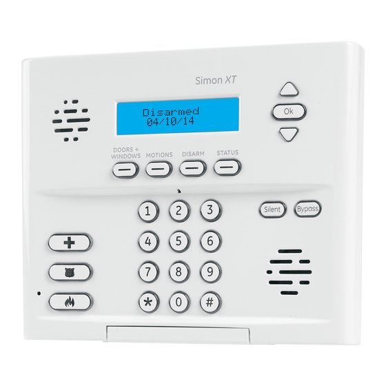
Simon XT/XTi GSM Module V4
INSTALLATION GUIDE (ADC-200T-EVD-IS)
Introduction
The GSM Module V4 with firmware version 151 & up for Simon XT and XTi
enables wireless reporting of all alarms and other system events from the GE
Simon XT and XTi control panels using an all-digital, GSM/GPRS wireless
(cellular) network. The module can be used as the primary communication
path for all alarm signaling, or as a backup to a telephone line connection to
the central monitoring station. The wireless alarm signaling and routing
service is operated by Alarm.com. The V4 module also features integrated
support for Alarm.com's emPower
capabilities.
The module interfaces with the Simon XT and XTi panel boards, fits into a
special compartment inside the panel, and is powered by the control panel
and panel battery.
Contact Information
For additional information and support on Alarm.com products and services,
please visit
www.alarm.com/dealer
at 1-866-834-0470.
Copyright © 2012 Alarm.com. All rights reserved.
Power Up
Reconnect panel battery and AC power. When a GSM module is connected
to a powered control panel, the LEDs at the bottom of the module will
become active. It may take a few moments after power up for the LEDs to
become active. If the LEDs do not light up at all, ensure that the module has
been fully inserted into the connector beneath it then perform a full power
cycle by following these steps:
1) Disconnect the battery leads and unplug the panel power transformer
from AC power.
2) Verify that the module is inserted securely and that the antenna is
snapped-in completely.
3) Connect battery leads to the battery. On the XT, make sure to observe
polarity (red to + and black to –) and to keep the wires outside of the tab
holding them in place.
4) Plug the panel power transformer into the AC outlet.
It is important to plug the battery in before plugging in the transformer,
otherwise the panel will issue a "System Low Battery" message regardless of
the battery voltage level.
Troubleshooting LEDs
Status LEDs indicate network and module status. Figure 1 below shows the
location of the status LEDs on the GSM module.
Figure 1: Status LEDs
TM
solution with built-in Z-Wave
or contact Alarm.com technical support
L5
L1 L2 L3 L4
Copyright © 2012 Alarm.com
Simon XT/XTi GSM Module V4 (ADC-200T-EVD-IS)
Table 1 below describes the LED functions.
Table 1: LED Functions
LED
Function
L1
Error LED. Flashes 1 to 8 times in an 8-second interval to indicate
specific error. See Table 2 Error! Bookmark not defined. for errors
and common fixes.
L2
Panel Communication and Z-Wave status messages. Flashes every
time the module communicates with the panel and flashes in
patterns to indicate Z-Wave status.
L3
GSM Communication. Flashes every time the GSM signal level is
checked and when packets are exchanged with Alarm.com.
L4
GSM Signal Level. Flashes 0 to 5 times to indicate signal strength, or
toggles on/off slowly when communicating with Alarm.com servers.
L5
Z-Wave Error LED. See Table 3 for error descriptions.
LED Details
LED L1 (red)
L1 flashes when there is an error. The number of flashes indicates the error
number. If there are two or more errors at the same time, the errors will
flash one after the other. The LED will stay off for at least four seconds
between errors.
Table 3: Errors flashed on L1 (red)
Number of
Error and solution
flashes
1
Module cannot communicate with the panel. Perform a power
cycle on the panel. If the error persists lift the module out of
the panel and re-insert it. If the error is still observed try a
different module. Finally, if that does not fix the problem try a
different panel.
2
The SIM card is missing. The SIM card holder can be found on
the module. Verify that the SIM card holder is closed securely
and that there is a SIM card in the holder.
3
The module is trying to register on the GSM network. If it
persists for more than a few minutes, the module is having
problems registering with the GSM network. Check L4 for
signal level. If signal level is lower than 2 "bars", change the
panel's location or use a remote antenna option. If the signal is
good, the module may be roaming on a GSM network that
does not partner with our GSM providers, or the SIM card was
not activated yet because the Alarm.com account was not
created correctly.
4
The module is registered on the GSM network but cannot
connect with Alarm.com. Contact Alarm.com Technical
Support.
5
Radio portion of the module is not working correctly. If this
persists for more than a few minutes the module may need to
be replaced. This error is extremely rare so verify that the
module is flashing 5 times.
6
This is an error only if it persists for more than a minute.
Otherwise, it's just an indication that the module is fixing an
unusual condition regarding communication with the GSM
network.
7
The module is not compatible with this panel type. Please
insert a compatible module.
8
If it persists, the account may have been set up incorrectly.
Contact Alarm.com Technical Support. You will be asked to
check the serial number of the module.
|
www.alarm.com
|
1-1-4.5-120706-EN
|
Installation
Guide
1
Advertisement

Subscribe to Our Youtube Channel
Related Manuals for Alarm.Com Simon XT


Summary of Contents for Alarm.Com Simon XT
- Page 1 Introduction Error LED. Flashes 1 to 8 times in an 8-second interval to indicate The GSM Module V4 with firmware version 151 & up for Simon XT and XTi specific error. See Table 2 Error! Bookmark not defined. for errors and common fixes.
- Page 2 • The module just powered up; • There is no GSM coverage in the area. Alarm.com recommends a steady • Reorient or relocate the receiving antenna. signal level of 2 or higher for proper operation of the module.
- Page 3 Simon XT/XTi GSM Module V4 (ADC-200T-EVD-IS) Installation Guide • Increase the separation between the equipment and receiver. • Connect the equipment into an outlet on a circuit different form that which the receiver is connected • Consult the dealer or an experienced radio/TV technician for help.
Need help?
Do you have a question about the Simon XT and is the answer not in the manual?
Questions and answers