
Summary of Contents for EarthLinked AVS Series
-
Page 1: Table Of Contents
® EarthLinked AVS Series Air Handlers Installation Manual for R-410A SC and SD Compressor Units in Heat/Cool or Cool Only Applications CONTENTS PAGE Pre-Installation Electrical Connections and Air Flow AVS Dimensions and Electrical Ratings Thermal Bulb Location and Field Conversion Service Parts Manufacturer’s Installation Instructions... - Page 2 READ THE SYSTEM INSTALLATION MANUAL FOR ADDITIONAL DETAILS. Earthlinked Technologies shall not be liable for any defect, unsatisfactory performance, damage or loss, whether direct or consequential, relative to the design, manufacture, construction, application or installation of the field specified components.
-
Page 3: Pre-Installation
These air handlers are for application to Heat/Cool and Cool Only applications! Upon receipt of the air handler, carefully check the Earthlinked Technologies model number on the package and on the air handler unit against the air handler model ordered. -
Page 4: Electrical Connections And Air Flow
AVS Electrical Connections and Air Flow The variable speed AVS Series air handler control board and field wiring diagram are illustrated in Figure 1. Figure 5. AVS Series Air Handler Control Panel and Field Wiring The blower speeds can be adjusted by changing the jumper settings on the control board as appropriate. - Page 5 1795 1795 2481 2481 2475 2464 2417 2441 2441 2441 2435 2399 AVS-0068-CV (“+” adjustment) 2327 2327 2327 2321 2315 2081 2081 2081 2081 2075 Figure 6. AVS Series Variable Speed Air Handler – Air Flow AVS-410CH-IM (10/13) Page 5...
-
Page 6: Avs Dimensions And Electrical Ratings
AVS Dimensions and Electrical Ratings AVS-410CH-IM (10/13) Page 6... -
Page 7: Thermal Bulb Location And Field Conversion
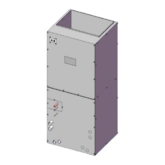
Figure 7. AVS Series Variable Speed Air Handler Dimensions and Electrical Ratings. Thermal Bulb and Field Conversion The air handler is shipped from ETI as it was ordered, either for vertical or horizontal installation. Figure 8 illustrates an air handler shipped from the factory with the TXV thermal bulb attached to the suction tube. - Page 8 The thermal bulb must be located and clamped to a HORIZONTAL extension of this suction tube, with options for the suction tube extension illustrated in Figure 9. This shows the suction tube directional options for an air handler that is to be installed in the VERTICAL direction. Figure 9.
- Page 9 Figure 10 illustrates locating the thermal bulb on the suction line extension. It shall be located at least 6 inches downstream of any fitting or bend in the suction tube extension, and at the 3:00, 4:00, 8:00 or 9:00 o’clock positions. Figure 10.
- Page 10 Clamp the thermal bulb firmly against the clean suction tube extension and parallel to it, as shown in Figure 11, to ensure good thermal contact along the entire length of the thermal bulb. Figure 11. Clamp the Thermal Bulb to the Suction Line Extension AVS-410CH-IM (10/13) Page 10...
- Page 11 After the thermal bulb is secured with the clamp, wrap the provided insulation around the thermal bulb and suction tube extension to isolate the thermal bulb from the surrounding air as shown in Figure 12. Apply the wire tie to hold the thermal bulb tube secure against the suction line as shown in Figure 12. Figure 12.
- Page 12 Figure 13. Typical Air Handler/Cased Coil After Conversion AVS-410CH-IM (10/13) Page 12...
-
Page 13: Service Parts
Service Parts Order TXV subassemblies for the AVS air handlers from Earthlinked Technologies, by the following numbers: COMPRESSOR UNIT AIR HANDLER MODEL TXV SERVICE PART NO MODEL/CAPACITY -024 (24,000 BTUH) AVS-0024-C* TXV-024C -036 (36,000 BTUH) AVS-0036-C* TXV-036C -048 (48,000 BTUH) -
Page 14: Manufacturer's Installation Instructions
AVS-410CH-IM (10/13) Page 14... - Page 15 AVS-410CH-IM (10/13) Page 15...
- Page 16 AVS-410CH-IM (10/13) Page 16...
- Page 17 AVS-410CH-IM (10/13) Page 17...
- Page 18 AVS-410CH-IM (10/13) Page 18...
- Page 19 AVS-410CH-IM (10/13) Page 19...
- Page 20 AVS-410CH-IM (10/13) Page 20...
- Page 21 AVS-410CH-IM (10/13) Page 21...
Need help?
Do you have a question about the AVS Series and is the answer not in the manual?
Questions and answers