Table of Contents
Advertisement
Quick Links
Advertisement
Table of Contents

Summary of Contents for Cutler-Hammer IQ Analyzer
- Page 1 C u t l e r- H a m m e r IQ Analyzer START Q U I C KS TA RT G U I D E...
-
Page 2: Troubleshooting
Use this Guide to begin performing basic metering functions quickly, without reviewing complete instructions provided in the User’s Manual. To more fully understand the wide array of features offered by your IQ Analyzer, it is strongly recommended that operators read the User’s Manual. Programming... -
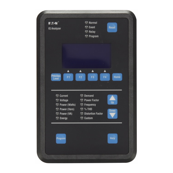
Page 3: Operator Panel
Operator Panel Introduction Introduction (USER’S MANUAL SECTIONS 1&2) (USER’S MANUAL SECTION 3) The IQ Analyzer is a compact, panel mount- ed, micro-processor based device for users who want to monitor all aspects of their electrical distribution system. It has been Function... -
Page 4: Modes Of Operation
Display Mode: (USER’S MANUAL SECTIONS 5-2) Current • Phase A, B, C, Average T h e IQ Analyzer monitors and displays a compre- • Neutral • Ground hensive list of metered parameters. The Meter Menu (separate CT inputs for each) -
Page 5: Manual Capture
Mounting (USER’S MANUAL SECTIONS 4-2) (USER’S MANUAL SECTIONS 5-1) When the IQ Analyzer is initially powered up, it is in Display Mode. The “Normal LED” will blink The IQ Analyzer is typically mounted on an green and the “Current LED” will glow red. The enclosure door. - Page 6 (USER’S MANUAL SECTIONS 4-3) Wiring procedures must be performed only by qualified personnel who are familiar with the Wiring installation for the IQ Analyzer must IQ Analyzer and its associated electrical equipment. follow a suitable Wiring Plan Drawing and Ensure that incoming ac power (or foreign power)
- Page 7 During initial setup of your IQ Analyzer, 3 Phase/3 Wire 1 Phase/2 Wire use Steps 1 - 5 below after the IQ Analyzer Phase Rotation has been mounted and wired using Sections (if Step 1 was 3 Phase, select one)
-
Page 8: Programming Example
NOTE: The IQ Analyzer must be programmed to C, N OF IQ ANALYZER Displayed (100 TO 600 VAC): a PT ratio of 120/120 or unity for the IQ Analyzer 4 8 0 --> UP DOWN ENTER to recognize there are no PTs. - Page 9 Time/Date Programming Example Password Programming Example From Main Menu Use F1-F4 PBs to Press and Release Move and Select Use F1-F3 PBs to From Main Menu Program PB Change Password Move and Select Press and Release Program PB Parameter to Change 5 Digit Password Top Level Entry Screen Displayed...
- Page 10 Blown or loose •Verify line voltage with possible wiring error(s). ge phases read fuse(s). multimeter. Check • Verify that IQ Analyzer ncorrectly. power module fuse(s) setpoint matches actual on affected phase(s) system phasing. located just above the •...
- Page 11 C u t l e r- H a m m e r For additional information or technical assistance, contact: ADVANCED PRODUCT SUPPORT CENTER 1-800-809-2772 w w w . c u t l e r h a m m e r . e a t o n . c o m...
Need help?
Do you have a question about the IQ Analyzer and is the answer not in the manual?
Questions and answers