Advertisement
Quick Links
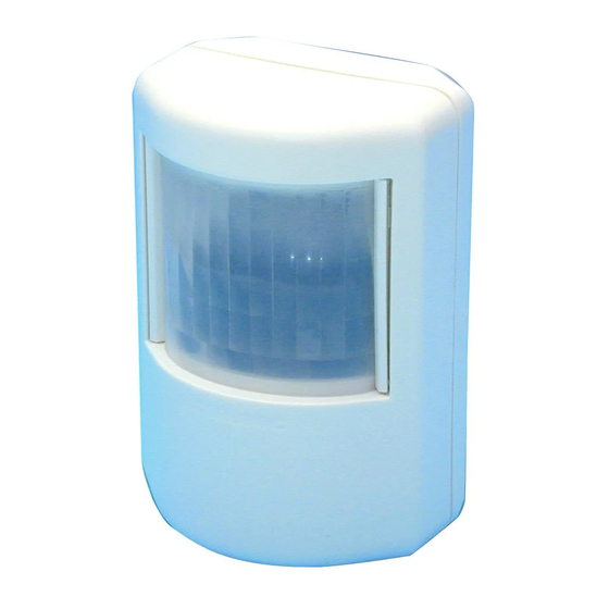
PRESENCE DETECTOR PD-2200 and PD-2400
1. Introduction
The detector is a passive infra-
red detector for presence detec-
tion. It has a very sensitive dual-
element, low-noise pyroelectric
detector. Electronics and softwa-
re in microprocessor is special-
ly constructed for presence de-
tection.
PD-2200 requires a 10–16 VDC
supply.
PD-2400 requires a 24 VDC/
VAC supply.
NOTE! PD-2400 is primarily in-
tended for presence detection
in systems for ventilation control
where 24 VDC is used.
PD-2400 must not be used in systems for lighting control, since
other components of such a system (logic modules, level selec-
tors, etc) are designed for 12 VDC operation and cannot there-
fore be easily combined.
In systems for lighting control by presence detection, the PD-2200
IR detector should be used, as this is designed for 12 VDC operation!
Software will analyse the signal from the pyroelectric detector
and measure noise level and signal power and sum of pulses.
Counting the pulses is a slower method that detects presence in
a locality with low activity with week signals as a result.
With a switch you can alter the signal process to be adapted to pre-
mises with high or low activity. A build in photocell can be used for
blocking the switching light on function when there is enough daylight.
The lens in the detector, collects heat radiation from different
fields, in to the sensor element. There are several different lenses
for different type of premises (office, corridor, and culvert a.s.o).
When a person passes cross over one field, there will be a strong
signal in the sensor element. When one moves along the field
(away from or toward the detector) in its direction, will also a
signal occur, but weaker.The detector should therefor be pla-
ced so one passes across (90º) through the lens field. Corner
placing of the detector is more or less always the most optimal.
(See handbook for "Presence Detection" for placing advice)
Extronic Elektronik AB | 08 609 29 00
Installation instructions
Art. No. 13140 / 13144
1
2. Connection – Adjustment.
Opening of the front. The cover opens in the middle at the top or
underneath with a screwdriver that turns. See picture!
Terminals
Relay; NO (Normal Open), C
(Closed), C (Common), NC
(Normal closed).
Change over contacts. At detec-
ting C and NO close. After cho-
sen time laps, contact C and NO
in relay open.
Voltage supply; + -
After connection it takes up to two minutes until the detector is
stabilized and works correct.
PD-2200: Detector requires 10–16 VDC. A suitable power supp-
ly is the EXE-2000.
PD-2400: Detector requires 15-26 VAC/18-37 VDC.
TP; Test-Point 0-5 VDC
Measure the voltage with a digital multimeter connected bet-
ween - and TP on PD-2200, or between the two metering points
marked TP on PD-2400. This measures the signal strength.
If a digital multimeter is connected and voltage between – and TP
is measured, is that a measure of signal strength.
The sensitivity adjustment does not effect this signal output.
•
At low noise level you can await a voltage level not over 0.3
VDC.
•
At strong detection, the voltage level is at close 5V.
•
At maximum sensitivity lies the trigger level at 0.6 V.
2016-11-04
Advertisement

Related Manuals for Extronic PD-2200

Summary of Contents for Extronic PD-2200
- Page 1 TP; Test-Point 0-5 VDC Measure the voltage with a digital multimeter connected bet- ween - and TP on PD-2200, or between the two metering points marked TP on PD-2400. This measures the signal strength. If a digital multimeter is connected and voltage between – and TP is measured, is that a measure of signal strength.
- Page 2 (lens 51). All lenses are described in handbook for “Presence Detection”. “Occupancy Activity” (different activity) PD-2200/-2400 are supplied as standard with lens no. 15. With 58 fields in 3 layers. Detection area is 40 x 40 meters and suita- •...
- Page 3 5. Signal analyse If you can answer yes to all the questions in the checklist then you can continue with commissioning. PD-2200/-2400 with microprocessor analysing the signals from • Check the voltage and polarity, and connect the power the pyroelectric detector has algorithms that continuous counts supply.
- Page 4 “see” potenti- ge. Use with precaution. al sources of interference. Contact Extronic for further advice and information when a Remove BL-1 after adjustment. Reset the LED switch to the re- bracket is used.
Need help?
Do you have a question about the PD-2200 and is the answer not in the manual?
Questions and answers