Table of Contents
Advertisement
Quick Links
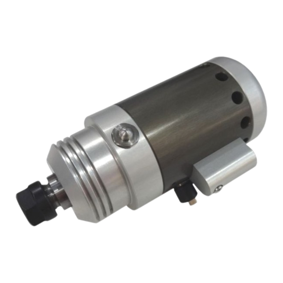
Spindle HF350 / HF500
Call for consumer information
Customers from outside the U.S.
STEPCRAFT GmbH & Co. KG
An der Beile 2
58708 Menden
Germany
Phone: 0049-2373-179 11 60
E-mail: info@stepcraft-systems.com
Customers from the U.S. / Canada
STEPCRAFT Inc.
59 Field Street, Rear Building
Torrington, CT, 06790
United States
Phone: 001-203-5561856
E-mail: info@stepcraft.us
IMPORTANT: Read before using
Operating/Safety
Instructions
Original Operating/Safety
Instructions
Date of: 22-08-2017
1
Advertisement
Table of Contents

Related Manuals for STEPCRAFT HF350


Summary of Contents for STEPCRAFT HF350
- Page 1 IMPORTANT: Read before using Operating/Safety Instructions Spindle HF350 / HF500 Call for consumer information Customers from outside the U.S. STEPCRAFT GmbH & Co. KG An der Beile 2 58708 Menden Germany Phone: 0049-2373-179 11 60 E-mail: info@stepcraft-systems.com Customers from the U.S. / Canada STEPCRAFT Inc.
- Page 2 All instructions, warranties and other collateral documents are subject to change at the sole discretion of STEPCRAFT, Inc. For up-to date product literature, visit www.stepcraft-systems.com for customers from Europe or www.stepcraft.us, for customers from US / Canada and click on the service & support tab for this product. Meaning of Special Language The following terms are used throughout the product literature to indicate various levels of potential harm when operating this product: The purpose of safety symbols is to attract your attention to possible dangers.
- Page 3 Electrical safety Power tool plugs must match the outlet. Never modify the plug in any way. Do not use any adapter plugs with earthed (grounded) power tools. Unmodified plugs and matching outlets will reduce the risk of electric shock. Avoid body contact with earthed or grounded surfaces such as pipes, radiators, ranges and refrigerators.
- Page 4 Service Have your power tool serviced by a qualified repair person using only identical replacement parts. This will ensure that the safety of the power tool is maintained. Safety Rules for Rotary Tools Make sure that the power tool cannot cut its own cord, therefore never install the power cord across the machine table.
- Page 5 Certain cleaning agents such as gasoline, carbon tetrachloride, ammonia, etc. may damage the surface. Risk of injury to user. The power cord must only be served by a STEPCRAFT service facility. Some dust created by power cutting, routing, milling, drilling, and other construction activities contains chemicals known to cause cancer, birth defects or other reproductive harm.
- Page 6 Symbols IMPORTANT: Some of the following symbols may be used on your tool. Please study them and learn their meaning. Proper interpretation of these symbols will allow you to operate the tool better and safer. Symbol Name Designation / Explanation Volts Voltage (potential) Amperes...
-
Page 7: Table Of Contents
Content GENERAL INSTRUCTIONS ................9 Information and Explanations to the Operating Instructions ........9 Description of Components ..................9 Intended Use ......................9 Design and Function ..................10 Designation of the Individual Parts of the Spindle ........... 10 Designation of the Controller Components ............. 10 Start-up ......................11 Clamping the Spindle ..................... - Page 8 Maintenance Information ..................19 Service ........................19 Cleaning ......................... 19 Extension Cords ..................... 19 Failure ........................20 Response to Malfunctions ..................20 Annex .........................20 Warranty and Service Contact information ............. 20 Manufacturer ......................21 Type Plate ......................21 Copyright ........................ 21 Limited Warranty ....................21 Instructions for Disposal of WEEE by Users of the European Union .......
-
Page 9: General Instructions
For more information on optional accessories, see item 3.5 of this manual. NTENDED The STEPCRAFT HFS has been developed for private users (e. g. model designers) and for single or small batch production in the commercial sector. It is not suitable either for large-scale production or for integration into assembly lines. -
Page 10: Design And Function
2 = Engine on / off switch 3 = Rotational speed "manual" setting 4 = Rotational speed display in % 5 = Main switch 6 = Signal input (STEPCRAFT system bus) 7 = Spindle screw jack 8 = Power supply... -
Page 11: Start-Up
ONNECTION OF THE ONTROL UNIT Connect the control unit to the system output of your STEPCRAFT Desktop CNC System using the supplied 15- pin Sub-D connection cable. NOTICE: If you have a CNC router from a different brand check the external documentation to connect the spindle to the data output of the specific CNC router (see also item 5.3) -
Page 12: Emergency Stop
3.4 E MERGENCY The emergency-stop switch is located on the front of the machine (see figure in item 3.1 STEPCRAFT 3D Desktop Operating Instructions). Pressing the switch triggers an emergency stop of the machine´s operation. Simultaneously, the power supply to the control system is interrupted. -
Page 13: Operator Control / Spindle
Type of tool Technical specification Applications End mill 2-flute fish - Solid carbide-end mill Ø1.0 mm - Universally applicable - Double-flute - Aluminum - Fishtail bottom - Plastics - Upcut- or downcut spiral - Wood End mill diamond - Solid carbide-end mill Ø1.0 mm - Glass fiber - Diamond toothed - Carbon fiber... -
Page 14: Spindle
Settings for approximate revolutions Switch setting Speed range 20% of the maximum speed, approx. 4,000 RPM 40% of the maximum speed, approx. 8,000 RPM 60% of the maximum speed, approx. 12,000 RPM 80% of the maximum speed, approx. 16,000 RPM 99% of the maximum speed, approx. -
Page 15: Replacing The Collets
4.5.1 PERATION The emergency-stop switch is located on the front of the STEPCRAFT Desktop CNC System. Pressing the emergency button leads to an emergency stop of the machine and the HFS. The machine will stop immediately. Actuate the emergency-stop switch only in emergency situations. -
Page 16: Testing The Spindle On / Off And Emergency-Stop Functionality
NOTICE: For questions regarding the control software, please contact the respective software developer. Manual test: Start the control software of the CNC router / STEPCRAFT Desktop 3D System. Mount the spindle on the tensioning system of the machine. Switch on the HFS controller, an audible confirmation can be heard. Do not start the spindle. - Page 17 Ultimately, the best way to determine the correct speed and feed for work on any material, is to practice on a piece of scrap, even after referring to the chart. You can quickly learn that a slower or faster speed / feed is more effective, just by observing what happens during processing a pass or two at different speeds / feeds.
-
Page 18: Technical Specifications
ECHNICAL PECIFICATIONS IMENSIONS AND EIGHT OF THE PINDLE Length: 130 mm Diameter: 52 mm Weight: 0.65 kg Clamping neck: 43 mm (Euro neck) Cable length: approx. 2 m / 6 feet THER HARACTERISTICS OF THE PINDLE Collet diameter: ER11, max. 8.0 mm Housing: Aluminum 7075 anodized, Type of the engine:... -
Page 19: Storage
AINTENANCE NFORMATION ERVICE To ensure continued enjoyment of your STEPCRAFT HFS, handle it carefully. Regular maintenance positively affects the life expectancy of the device. Preventive maintenance performed by unauthorized personnel may result in misplacing of internal wires and components which could cause serious hazard. We recommend that all tool service be performed by a STEPCRAFT service facility. -
Page 20: Failure
ARRANTY AND ERVICE ONTACT INFORMATION Country of STEPCRAFT Address Phone no. / E-mail address Purchase United States of STEPCRAFT Inc. 733 E Main St. Unit 3 +1 203 556 1856 America Torrington, CT, 06790 info@stepcraft.us Germany STEPCRAFT An der Beile 2 +49 2373 179 11 60 GmbH &... -
Page 21: Manufacturer
(iii) modification of or to any part of the product, (iv) attempted service by anyone other than a STEPCRAFT authorized service center, (v) products not purchased from an authorized STEPCRAFT dealer, or (vi) products not compliant with applicable technical regulations. - Page 22 You must include this request with your items submitted for service. Non-warranty service estimates will be billed a minimum of ½ hour of labor. In addition you will be billed for return freight. STEPCRAFT accepts money orders, cashier´s checks as well as credit cards and PayPal payment. By submitting any item to STEPCRAFT for service, you are agreeing to STEPCRAFT`s Terms and Conditions found on our website (see contact details on front page).
-
Page 23: Instructions For Disposal Of Weee By Users Of The European Union
9.7 R HS, 2002/95/EG We confirm that the STEPCRAFT HF Spindle complies with the RoHS, 2002/95/EC. -
Page 24: Ec-Declaration Of Conformity
9.8 EC-D ECLARATION OF ONFORMITY Copyright © STEPCRAFT...
Need help?
Do you have a question about the HF350 and is the answer not in the manual?
Questions and answers