
Summary of Contents for VisionTrack VT3000-AI
- Page 1 VT3000-AI INSTALLATION GUIDE THE UK'S MOST AWARD-WINNING CAMERA TELEMATICS COMPANY www.visiontrack.com...
-
Page 2: Table Of Contents
3.1 VT3000-AI Installation 3.2 VT3000-AI Camera Calibration 3.2 VT3000-AI Camera Calibration 3.4 DSM Camera FOV 3.5 DSM Calibration 3.5 Install the IPC Cab Camera (if applicable) Speed Signal Commissioning t +44 (0) 1246 225 745 | e orders@visiontrack.com | w visiontrack.com... -
Page 3: Important Information
Approved Accreditation Bodies and may also affect the vehicle manufacturers warranty. To avoid interference the VisionTrack power supply MUST be installed as far away as possible from other telematics devices and power supplies already installed within the vehicle. -
Page 4: Overview
Moni or river beh vio r from S ppor s GPS n GLONASS n where sing he VisionTr ck receiver wi h self-checking IoT pl form no ific ions t +44 (0) 1246 225 745 | e orders@visiontrack.com | w visiontrack.com... -
Page 5: System Diagram
VT3000-AI INSTALLATION GUIDE 1.1 System Diagrams VT-670-FHD-IPC VT-C26-IPC VT-R Watch V2 VT-DSM-AI IO Power Serial CAN VT3000-AI VT3000-AI Main Cable t +44 (0) 1246 225 745 | e orders@visiontrack.com | w visiontrack.com... -
Page 6: Packing List
VT-R Watch V2 Wipe SD Card Standard SIM Card VT-EASYCHECK J1939 Connector 6-PIN IPC Extension 2A Mini-blade Cable 3m Fuse *Con en s s bjec o ki p rch se t +44 (0) 1246 225 745 | e orders@visiontrack.com | w visiontrack.com... -
Page 7: Required Tools
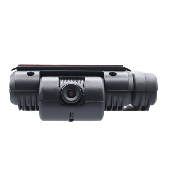
Cable Ties Drill Marker Pen USB Flash Drive Wire Cutter Wire Stripper (Optional) Self Tapping Screws Allen Keys 5M/50M Tape Measure Crimping Tool Electrical Tape Multimeter Amalgamating Tape t +44 (0) 1246 225 745 | e orders@visiontrack.com | w visiontrack.com... - Page 8 VT3000-AI INSTALLATION GUIDE 1.4 VT3000-AI Features: Windscreen Bracket Camera Lens SIM Card/SD Card Panel (Locked) Lens adjustment SIM Card/SD Card Panel (Unlocked) USB Port Loudspeaker t +44 (0) 1246 225 745 | e orders@visiontrack.com | w visiontrack.com...
-
Page 9: System Installation Overview
*When mo n e lower own he win screen, ll c bles nee o be mo n e he op of he win screen. 2.2 Power Supply, Ignition & IO Signal t +44 (0) 1246 225 745 | e orders@visiontrack.com | w visiontrack.com... -
Page 10: Speed Signal & Serial Ports
2.4 Install SIM & SD Cards Standard size SIM card: Check the SD card’s write protection switch, which should be in the “on” position. Check “write enable” of SD Card t +44 (0) 1246 225 745 | e orders@visiontrack.com | w visiontrack.com... - Page 11 Remove the bracket from the rear to enable install, (slide top to remove). Remove the cover and install the SD card and SIM card**. **This m be one for o . t +44 (0) 1246 225 745 | e orders@visiontrack.com | w visiontrack.com...
-
Page 12: Vt3000-Ai Installation
3.1 VT3000-AI Installation IMPORTANT: Degrease and clean the windscreen before attaching. The VT3000-AI should be mounted in the middle at the top of the window screen, ensuring the lens is within the swept area of the wipers. All cables should be going towards the roof. -
Page 13: Vt3000-Ai Camera Calibration
Then place a 2.5m high reference point in front of the lens that is 5m away. (Please note the ED might change when the camera is installed higher) Open the settings of the VT3000-AI, enter the ADAS camera install height (AC) in the "Algorithm" menu (Easycheck APP). - Page 14 30m reference line up with the reference point DE as mentioned above*. *Yo m nee VT Commission S ppor for his s ep. Refer o he Commissioning sec ion on p ge 19. t +44 (0) 1246 225 745 | e orders@visiontrack.com | w visiontrack.com...
- Page 15 VT3000-AI INSTALLATION GUIDE Finish the ADAS camera calibration by changing it to Normal mode then click ok. t +44 (0) 1246 225 745 | e orders@visiontrack.com | w visiontrack.com...
- Page 16 Secure the camera AFTER finishing the calibration. The DSM camera should mount 70 – 120cm between the driver’s eyes. t +44 (0) 1246 225 745 | e orders@visiontrack.com | w visiontrack.com...
-
Page 17: Dsm Camera Fov
Keep the device name as "DSM" and select "Calibration", set "Front" or "Side" depending on the installation location. *Yo m nee VT Commission S ppor for his s ep. Refer o he Commissioning sec ion on p ge 19. t +44 (0) 1246 225 745 | e orders@visiontrack.com | w visiontrack.com... -
Page 18: Install The Ipc Cab Camera (If Applicable)
Finish the driver camera calibration by changing it back to “Normal mode” then secure on the dashboard. 3.5 Install the VT-C26-IPC Cab Camera (if applicable) Install the IPC camera inside the driver's cab, FOV example shows in figure below: t +44 (0) 1246 225 745 | e orders@visiontrack.com | w visiontrack.com... -
Page 19: Speed Signal
Satellite GPS speed may have latency that may affect the accuracy of the alarms, but it is acceptable for most applications. Find the "Satellite" in the "Speed" menu. t +44 (0) 1246 225 745 | e orders@visiontrack.com | w visiontrack.com... -
Page 20: Commissioning
Friday and 9am - 5pm on a Saturday. You will be given a Camera Commissioning Number by the Commissioning Team. It is very important that the commissioning number is recorded on your Job sheet/ticket. t +44 (0) 1246 225 745 | e orders@visiontrack.com | w visiontrack.com... - Page 21 VT3000-AI INSTALLATION GUIDE 2 Chapman Way High Brooms Industrial Estate Tunbridge Wells Kent TN2 3EF...
Need help?
Do you have a question about the VT3000-AI and is the answer not in the manual?
Questions and answers