Advertisement
Quick Links
I
:
NTRODUCTION
I
is a GPS-based video system designed for
NSPIRE
photography applications. Besides offering a remote
shutter interface for digital and film cameras, it also
provides detailed navigational information. The realtime
data is presented as a text overlay on the user's
existing video camera signal. In addition, the GPS data
for each photo can be stored for later review.
Although I
is designed for video and still
NSPIRE
photography, its applications do not stop there. It can
also be used in applications that serve the mapping
industry, hobby robotics, ham radio, radio control
modeling, and other commercial/hobby uses. In non-
GPS applications, it can be used for video telemetry
monitoring of voltages, current, tach-speed, radio
performance, and more.
The main module's weight is approximately 3 ounces
(85 grams) and the size is 4.0" x 2.4" x 0.4". A
compatible 0.5 ounce (16 gram) micro-sized GPS
receiver allows for a low overall weight.
Flexible power requirements allow operation on as little as 6VDC at ~185mA. The On-Screen
Display (OSD) video format is NTSC/RS-170. A PAL/CCIR compatible video version is available
upon special request.
S
:
FEATURE
UMMARY
#
Clock/Timer can display local time, UTC time, or elapsed time.
#
Remote operation of data display and camera shutter.
#
R/C Glitch counter can capture up to 999 glitch events.
#
Data recorder can capture GPS information on up to 999 Photos/Events.
#
Displayed GPS altitude can be MSL or AGL. Accurate ground referenced speed.
#
Tachometer provides real time display of RPM (up to 65K RPM).
#
Interval-based station ID (ham call sign or station name).
#
Real-time GPS based heading degrees, latitude and longitude.
#
GPS Waypoint bearing & steering indicators (user provided Garmin Geko GPS required).
#
Buffered GPS output provides NMEA sentences to external devices.
#
Export GPS records to your custom application via RS-232.
#
Displays up to 40VDC and current up to +/-50 amps continuous.
#
Displays radio system voltage.
I
V3.2 U
NSPIRE
SER
I
NSPIRE
On-Screen Display with GPS Telemetry
User Manual
Firmware Version 3.2
M
©2006
ANUAL
OSD
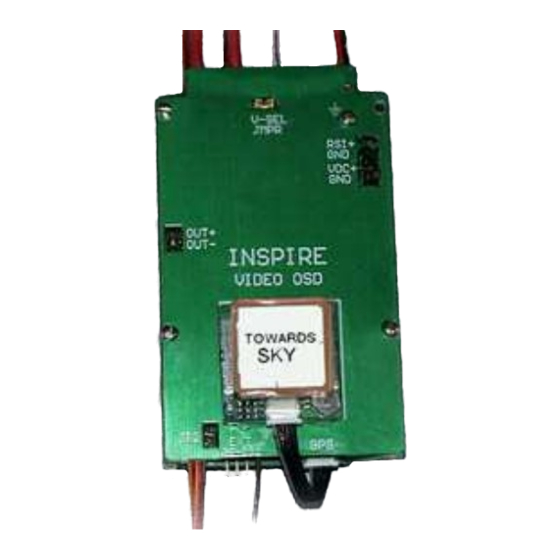
Figure 1, Inspire Board
Page 1
May-17-2006
Advertisement

Summary of Contents for Inspire OSD
- Page 1 0.5 ounce (16 gram) micro-sized GPS receiver allows for a low overall weight. Flexible power requirements allow operation on as little as 6VDC at ~185mA. The On-Screen Display (OSD) video format is NTSC/RS-170. A PAL/CCIR compatible video version is available upon special request. FEATURE UMMARY Clock/Timer can display local time, UTC time, or elapsed time.
- Page 2 Digital Products Company, or their distributors, have no control over the installation and use of the Inspire video system. As such, no liability may be assumed, nor will any liability be accepted, for any damages resulting from the use of this product. Under no circumstances will the buyer be entitled to consequential or incidental damages.
- Page 3 GPS option is used. Below it is the motor tachometer data (shown as 630 rpm). TATION The text field below the Altitude shows the station ID message (shown here as “Inspire OSD”). It appears at user specified intervals. This message can be easily edited and allows up to eleven characters.
- Page 4 4.9V -0.6A). This is valuable data for electric motor operation. The voltage can be configured with an alarm threshold for additional visual warning. The last data line shows the R/C system’s voltage (shown as 5.21V)) and the OSD board’s operating voltage (shown as 8.6V).
- Page 5 IDEO ONTROL The R/C-VID cable can be used to turn the OSD on/off from the R/C transmitter. This is a handy way to obtain a clear camera image for data-free video recording and viewing. While the OSD is off, any alarm condition (low voltage, lost R/C signal, glitches) will cause the OSD data to reappear.
- Page 6 Of course a camera does not need to be used with this feature. Perhaps your application will want to use the R/C transmitter only to store useful GPS data upon remote command. Lastly, a user-configured Event timer can be setup to periodically record the GPS data for you.
- Page 7 YSTEM EATURES ’s record storage and configuration features are NSPIRE accessed using special menus that are guided by the joystick. Entering the menu begins by pressing the joystick’s Enter button for three (3) seconds. Once you do that you will see the main System Features menu, as seen in Figure 5.
- Page 8 >Call menu item to initiate a connection. It is now ready to receive the GPS report (select Send GPS Report in Inspire’s menu). When complete, select Transfer->Capture->Stop on the menu bar. If you need further assistance using the utility please see the HyperTerminal help file.
- Page 9 YSTEM ET UP ’s default settings are configured in the System Set Up menu. To change the power-up NSPIRE defaults, highlight the S entry and then press the left or right joystick buttons. YSTEM ID S 1: The first screen you will see ESSAGE ETUP is ?Msg ID Setup Page 1,”...
- Page 10 2: Once you are satisfied with page 1, you can move to the next page by AMERA VENT pressing the joystick’s Enter button. This leads to the ?Camera/Event Page 2” configuration menu, as seen in Figure 10. Camera Mode The R/C-Aux channel input can be configured to operate a standard R/C Servo or it can provide a switched output for direct (hardwired) camera connection.
- Page 11 ATV/EPA mixing features to provide correct response to the displayed messages. In other words, when you want the OSD’s main screen video to be shown, the Video State should display ?On.” When you want enable the camera shutter, the Aux State should display ?On.”...
- Page 12 GPS F 3: This menu is used to configure the ORMAT GPS related parameters. Please see Figure 12. As with the other menus, the up/ down joystick buttons move the menu selection and the left/right buttons alter the menu entry. Coordinate Format The GPS coordinates can be displayed in Decimal or NMEA format.
- Page 13 GPS H 4: This menu is used to configure ARDWARE the GPS hardware related parameters, as shown in Figure 13. As with the other menus, the up/down joystick buttons move the menu selection and the left/right buttons alter the menu entry. GPS Module ID This entry is used to select the GPS Module type that is used.
- Page 14 5: This menu is used to configure I ’s miscellaneous features, as EATURE ETUP NSPIRE shown in Figure 14. As with the other menus, the up/down joystick buttons move the menu selection and the left/right buttons alter the menu entry. Tachometer Magnet Count The tachometer is based on a Hall Effect sensor that monitors shaft mounted magnets.
- Page 15 6: This menu is used to configure I ’s System Features, as shown in YSTEM ETUP NSPIRE Figure 15. As with the other menus, the up/down joystick buttons move the menu selection and the left/right buttons alter the menu entry. Screen Size The main screen’s size can be changed here.
- Page 16 YSTEM EATURES IDEO IELD ETUP The data fields are easily turned on or off, per your application requirements. Begin by selecting the Video Field Setup (found in the System Feature menu). Video Field Setup: Data Field Toggle You can move around the various fields by using the up/down joystick buttons.
- Page 17 Digital Products Company, or their distributors, have no control over the installation and use of the Inspire video system. As such, no liability may be assumed, nor will any liability be accepted, for any damages resulting from the use of this product. Under no circumstances will the buyer be entitled to consequential or incidental damages.
Need help?
Do you have a question about the OSD and is the answer not in the manual?
Questions and answers