
Summary of Contents for platypus PSCGen6-NO
- Page 1 Platypus Controller User Manual - Gen 6 PLATYPUS PLATYPUS PLATYPUS CONTROLLER CONTROLLER CONTROLLER Platypus Fire Pty Ltd makers of the The Sensible Bushfire Protection System...
-
Page 3: Table Of Contents
Contents Warning Symbols Explained......................... 1 Important Safety Instructions ......................1 Overview ..............................2 Read before operation .......................... 3 Installation ............................3 Safety Precautions ..........................3 RCM ..............................3 Home Screen ............................4 Password Screen ..........................5 System Screen ............................ 5 Auto/Manual Screen ........................ - Page 4 Off ..............................25 Evac ..............................26 Battery ............................. 26 Trouble Shooting ..........................27 Installation Notes ..........................28 Installing the Platypus Controller ..................... 29 Location ............................29 Mains Outlet ............................ 30 Switching loads greater than 12A ..................... 30 Terminals ............................31 External Temperature Sensor ......................
-
Page 5: Warning Symbols Explained
Refer all installation and servicing to qualified service personnel • Please read these instructions fully and carefully before using this controller. The Platypus Controller operate from 240 volts. Death or serious injury may result if this product is not correctly installed and operated. Platypus Controller ver-6.0.0... -
Page 6: Overview
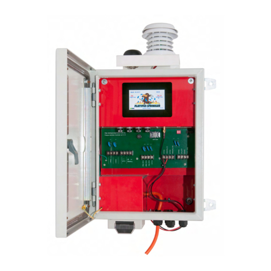
Overview The Platypus Controller is a powerful, flexible controller that can be configured in a variety of ways to control a pump(s) and watering systems. It can communicate with the user via SMS or manually from the on board touch screen. The Platypus Controller can be set to operate using the controllers intuitive program interface. -
Page 7: Read Before Operation
Read before operation Installation The Platypus Controller should be installed by a Platypus certified installer. This will ensure correct placement and operation of all components. Safety Precautions Keep this manual where an operator can easily locate it. • Read this manual prior to operating the equipment. -
Page 8: Home Screen
Touching anywhere on the Platypus logo will take the user to the Password screen. If more than 3 minutes elapses and the screen has not been touched the Platypus Sprinkler Controller will go to sleep. Sleep mode reduces the overall power consumption of the Platypus Sprinkler Controller. -
Page 9: Password Screen
(The Platypus Controller is delivered from the factory with the password set to "1234". The installer of the Platypus Controller may override this code with a new four(4) digit code. , which will be given to you at the time of installation.) If the entered four (4) digit code is valid, the controller display will go to the System screen. -
Page 10: Auto/Manual Screen
To exit the System screen at any time, touch the red Home button at the bottom right of the screen. Auto/Manual Screen From this screen the operator can select manual or automatic operation of the Platypus Sprinkler Controller. The green highlighted buttons indicate the current mode setting for the Platypus Controller. -
Page 11: Display Log Screen
The Max Temp entry refers to the maximum temperature recorded for the date shown in the log entry. The Box Temp entry indicates the maximum temperature inside the Platypus Controller enclosure for that day. The maximum daily temperature is added to the display log at 00:00:01 hours. -
Page 12: Cycle Times
Touch on "Up" repeatedly to increase the pump run time (max 60 minutes). Touch on "Down" repeatedly to decrease the pump run time. The pump run time displayed is the number of minutes the pump will run for when the Platypus Sprinkler Controller is in the auto mode of operation. -
Page 13: Set Trigger Level
On this screen the operator can select the trigger temperature at which the system will be activated. When the Platypus Sprinkler Controller is in the auto mode of operation and an ambient air temperature, equal to or above the preset trigger temperature is detected, any device connected to the Platypus Sprinkler Controller will be operated. -
Page 14: Change Password Screen
View System This screen displays the individual components that are installed to the Platypus Controller. Devices shown in green background are installed and will operate when the system is active. Devices shown in grey background are not installed and will not operate when the system is active. -
Page 15: Test System
"Delete" button will erase all messages from the system. Delete Back Battery Test battery is available if the battery function has been installed. When the battery function is selected the battery voltage and percent of charge will be displayed. Platypus Controller ver-6.0.0... -
Page 16: Set Clock/Date
Set Clock/Date On this screen the user can set the current time and date. After applying power to the Platypus Controller, it will be necessary to reset the time and date of the system clock. If the phone module and a sim card have been installed, the current date and time will be obtained from the telephone network. -
Page 17: Info
If more than 3 minutes elapses and no buttons on this screen have been pressed, the Controller will return to the home screen. Info This screen the displays an overview of the Platypus Controller settings. To exit the Info screen at any time, touch the red "Back" button at the bottom of the screen. -
Page 18: System
To exit the About screen at any time, touch the red "Back" button at the bottom of the screen. If more than 3 minutes elapses and no buttons on this screen have been pressed, the Controller will return to the home screen. Install Platypus Controller ver-6.0.0... - Page 19 On this screen the user can select the individual devices that are to be active on the Platypus Controller. To install a device, touch on the device name. The selected device will be activated. The selected device can be de-activated at any time by touching again on the device name.
-
Page 20: Access
If more than 3 minutes elapses and no buttons on this screen have been pressed, the Controller will return to the home screen. Diesel From this screen the parameter to be set on the diesel motor can be selected. Platypus Controller ver-6.0.0... - Page 21 The run signal delay time refers to the signal from the diesel motor that indicates the motor is running. This setting allows the installer to extend the time frame of the signal arrival to the Platypus Controller. Platypus Controller ver-6.0.0...
-
Page 22: Phone
If more than 3 minutes elapses and no buttons on this screen have been pressed, the Controller will return to the home screen. Phone From this screen the user can store the location at which the Platypus Sprinkler Controller is installed and the primary telephone number to which the Platypus Sprinkler Controller will send SMS data. -
Page 23: Location
To the "Location" screen at any time, touch the red "Back" button at the bottom of the screen. Primary Phone Number From this screen the user can enter the primary telephone number the Platypus Controller will send SMS data to. Primary Phone Number To enter a telephone number touch on "Primary Phone Number". -
Page 24: Additional Numbers
Evac The red evacuation button is located on the gland plate at the bottom of the Platypus Controller, see figure 1. Pressing this button will cause the Platypus Controller to become active for the time period set below. -
Page 25: Aux
When the "Aux" function is selected from the "Install" screen, the terminals labelled "NO Contact1" and "NO Contact 2" in figure 4 below, are shorted together by an internal relay. These contacts are rated at 2 amps. Figure 4: Terminal labels. Platypus Controller ver-6.0.0... -
Page 26: Active Screen
If the measured ambient air temperature is equal to or greater than the trigger temperature minus five degrees which has been set by the user, the Platypus Sprinkler Controller will again become active. Once the ambient air temperature is five(5) degrees less than the trigger temperature, the Platypus Controller will return to the home screen. -
Page 27: Pause Screen
Below this is displayed the pause time in minutes and the pause time remaining. If the Stop button on the PAUSE screen is touched, the Platypus Controller will cease all pumping operations and will switch to MANUAL mode. -
Page 28: Control Words For Sms Functions
Battery • The Platypus Sprinkler Controller will respond to the above control words. The spelling is critical, the case can be either upper or lower or a mixture of both. The control word should be sent as a text message(SMS) to the Platypus Controller. The Platypus Controller will respond with information relevant to the control word that was sent. -
Page 29: Auto
Text the control word "On" to the Platypus Controller. The Platypus Controller will switch to the Manual mode of operation and activate all installed devices. -
Page 30: Evac
Platypus Controller. Battery Text the control word "Battery" to the Platypus Controller. If the battery function has been installed, the Platypus Controller will respond with a text which describes the current charge state of the battery. -
Page 31: Trouble Shooting
Trouble Shooting Case Explanation System loading message is displayed If the phone option is installed the Platypus Sprinkler Controller for a long time when the power is first can take up to 90 seconds to initialize applied. Nothing is displayed on the screen The Platypus Sprinkler Controller has gone to sleep. -
Page 32: Installation Notes
To change the functions of this controller, please first read this installation guide. Please read these installation instructions fully and carefully before installing or servicing this controller. The Platypus Controller operates at 240 volts. Death or serious injury may result if this product is not correctly installed and operated. -
Page 33: Installing The Platypus Controller
Sprinkler Controller should be installed on a surface that is not exposed to the sun in the later part of the day. The area marked in blue on the compass in figure1 shows the preferred location of the Platypus Sprinkler Controller. -
Page 34: Mains Outlet
In cases where it is required to operate an electric motor greater than 2.8KW an external contactor can be used. This would plug in to the mains outlet on the Platypus Controller and would operate when the Platypus Controller activates the mains outlet. -
Page 35: Terminals
Terminals The photograph in figure 6 below shows the terminal labels and the wire colours the Platypus system uses for connection to the diesel motor, battery and low fuel systems. The two white wires connected to the Evacuate terminals are connected to the evacuate switch on the gland plate of the Platypus Controller. -
Page 36: External Temperature Sensor
External Temperature Sensor To connect the Platypus Controller to the external temperature sensor use CAT5 cable. The four coloured wires should be twisted together and the four white wires should be twisted together, as shown in figure 3 below. This arrangement will ensure minimum resistive loss over longer cable runs. -
Page 37: Specifications
Battery Charge 13VDC 1A Inputs 4* Analogue 8 to 12VDC 2*Analogue Thermistor 10K@25C Due to our continuing program of research and development the specifications herein may change without notice. • Specifications may differ from country to country. • Platypus Controller ver-6.0.0... - Page 38 High/Low 25mA per output Inputs 4* Analogue 8 to 12VDC 2*Analogue Thermistor 10K@25C Due to our continuing program of research and development the specifications herein may change without notice. • Specifications may differ from country to country. • Platypus Controller ver-6.0.0...
- Page 39 1.1 In this Warranty the following definitions apply: Date of Purchase has the meaning set out in clause 3.2. Platypus means Platypus Fire Pty Ltd (ACN 159 992 355) of PO Box 466, Trafalgar VIC 3824 Australia. Purchaser means the purchaser of the Controller.
- Page 40 Controller is of acceptable quality; and b. is free from defects. 2.5 Subject to clause 2.1 above and the terms and conditions of the Warranty, Platypus agrees to repair or replace, at Platypus’ expense the Controller purchased by the Purchaser in Australia directly from Platypus or from a Platypus authorised distributor if and when the product does not perform in accordance with the manufacturer’s specifications during the Term of the Warranty.
- Page 41 5.4 Replacement of the Controller does not extend the Term of the Warranty. 5.5 If the Controller was not installed by Platypus or its authorized agents, any travel costs or onsite labour costs incurred by Platypus to attend the property at which the Controller is installed to repair or replace the Controller will not be covered by the Warranty.
- Page 42 6.2 Platypus is not liable for any loss or damage arising from alterations to third party hardware or software. 6.3 Platypus is not liable for any loss or damage arising from loss of use, loss of profits or revenue. 6.4 Platypus is not liable for any loss resulting from indirect or consequential loss or damage.
Need help?
Do you have a question about the PSCGen6-NO and is the answer not in the manual?
Questions and answers