
Summary of Contents for AWC GP3
- Page 1 GP3 PC Analog/Digital I/O Kit For the latest documentation see http://www.awce.com/doclib.htm#gp3 © 2010-2015 by AWC, All Rights Reserved http://www.awce.com v1.6 15 April 2015...
-
Page 3: Table Of Contents
Table of Contents Overview..................................1 Documentation.................................1 If You Need Help..............................1 Details..................................1 Hardware..................................2 GP3X...................................2 GP3X Parts List..............................2 Construction Notes............................6 Raspberry PI-Compatible Notes........................7 Arduino-Compatible Notes..........................7 GPMPU28................................8 GPMPU28 Parts List............................8 GPMPU28 External Connections........................8 GPMPU40.................................10 GPMPU40 Parts List............................10 GPMPU40 Connections..........................11 GPMPU40 Edge Connector.........................12 Final Checkout..............................13 Software.................................13 Reference................................16 Quick Reference..............................20... -
Page 4: Overview
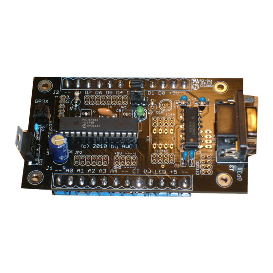
Overview The GP3 is the easiest way to interface a PC to the real world. You can also develop using your PC and then let the GP3 sense and control the real world on its own. This kit provides a hardware interface that allows you to easily monitor and control analog and digital circuitry. -
Page 5: Hardware
Interface – The whole point to the GP3 is to interface to the outside world. Each board has a variety of • methods to connect it to the outside world. The remainder of this manual will be divided into two major parts: Hardware and Software. The Hardware portion will discuss each board option in turn. - Page 6 DCE (default) DCE (default) If you are connecting the GP3 to a non-RS232 device like a microcontroller, you can use the TTLSER pins and remove IC2. The pins are: 1 – Handshaking in to GP3 (RTS) 2 – Handshaking out to GP3 (CTS) 3 –...
- Page 7 TTLSER pin 4 After testing the GP3-X, you may want to use a small zip tie to strain relief the cable by passing the zip tie through the two large holes in the unused J3 footprint, ensuring that the USB cable is encircled by the zip tie.
- Page 8 on any of the pins marked –) is sufficient to power the board (with all I/O quiescent, the board draws roughly 11 to 15 mA). If you prefer, you can install the regulator (IC3) and C6 and feed a higher voltage (usually 8 to 12V) into V+ on J2.
-
Page 9: Construction Notes
Or you could route a wire from an analog input to an op-amp in the spare IC4 socket and then back from the op-amp to the GP3's CPU. Note that on JP2, the 5th pin (near J1's A3) is not connected through and only connects to an unused GP3 pin. -
Page 10: Raspberry Pi-Compatible Notes
Important Note: Although the GP3X board has pins labeled +5V, when using the Raspberry PI- compatible version, these pins are at 3.3V. It will not hurt the GP3 to power it at 5V, but it may damage the host computer. -
Page 11: Gpmpu28
Vin/Gnd 9V battery snap The board requires no modifications to work with the GP3 However, you may want to consider any special power supply connections or serial connections you'd like to make. In addition, you'll need to connect the outside world to the GP3 as appropriate for your situation. - Page 12 Description JP1-9 Analog input #1 JP1-10 Analog input #0 JP1-11 Digital input/output #0 Digital input/output #1 Digital input/output #2 Digital input/output #3 Digital input/output #4 Digital input/output #5 ICSP-5 Digital input/output #6 ICSP-4 Digital input/output #7 Board assembly is straight forward. Install the shorter components such as the IC1 socket and IC2 first. Then install the smaller components such as the reset jumper, X1, R1, etc.
-
Page 13: Gpmpu40
9V battery snap or optional coaxial power jack The GPMPU40 board is not specifically designed for the GP3 – it is simply a general purpose board and you can read more about it in the GPMPU40 manual (see http://www.awce.com/doclib.htm#GPMPU40). The goal is to essentially duplicate the GP3X or GPMPU28 schematics (at the end of this manual) on the board. -
Page 14: Gpmpu40 Connections
Optional (brings unregulated voltage to JP2) JP7 is the run/program jumper. If you connect a shunt from pin 1 to 2 and reset the board, the GP3 will respond to commands from the PC. If you connect the shunt between 2 and 3 and reset, the GP3 will execute its preprogrammed script. -
Page 15: Gpmpu40 Edge Connector
1 and the even numbered pins are all on the other long row with pin 2 directly below pin 1. The connector along the edge (JP1+JP2 counts as one connector with pins 1 to 40) contains all the GP3 signals as seen in the table below. -
Page 16: Final Checkout
Software The GP3 connects to a PC or other host device via the RS-232 port. The GP3 is a DCE device, so you can use a straight cable to connect directly to a PC. The PC sends commands to the board using 57600 baud serial data. - Page 17 You can find more about different techniques to use the GP3 at http://www.awce.com/gp3intro.htm. The current methods available are: Method Description Pros Cons Links Not as flexible as conventional Info center Use a simple point and programming. Requires • Very easy to use.
- Page 18 Libraries to interface the Install like any • GP3/A to Arduino. Works Arduino library by Arduino with any GP3 board if copying into your Documentation • interfaced to Arduino. libraries folder Analog inputs read raw counts from 0 to 1023 (0 to 5V with the default reference) and have a maximum recommended source impedance of 10K.
-
Page 19: Reference
1 N N N N N N N Since this is only 7 bits, the convention is that the GP3 accepts the value divided by 2. The L bit from the command makes the entire 8 bit number. All communications are at 57600 baud, 8 bits, 1 stop bit, and no parity. - Page 20 – This function accepts an A/D channel number (from 0 to 4) and returns a 16-bit number that contains the 10-bit A/D result. The first byte sent by the GP3 is the top 8 bits of the result. Raw command: 0 0 1 1 P P P 0 where P P P is the A/D channel number.
- Page 21 LED off and X=1 to turn LED on. count - The count command allows the GP3 to count the number of low to high pulses that occur on an input pin over a particular period of time. This is not the hardware counter, but instead requires the GP3 to watch the input pin (the pin is forced to be an input).
- Page 22 – You can use the 0 1 0 1 1 0 0 L command to increment (L=1) or decrement (L=0) ARG. reset – The 0 0 0 0 0 0 0 0 command performs a quick reset that does not change any state, but resets the GP3's communication state.
-
Page 23: Quick Reference
Frequency in Hz (2 Hz for Pi), duration in milliseconds (2 mS units for Pi) setcounter prescale, mode none Set prescaler (1, 2, 4 or 8) and timer/counter mode resetall none none Reset GP3 repeat count none Repeat next command readbyte none byte Read bytes from repeated command... -
Page 24: Additional Prototype Space ("Wings")
Additional Prototype Space (“Wings”) AWC offers additional “wings” you can mount on either (or both) sides of the GP3-X to gain additional space to prototype. The boards are universal PCBs and, of course, you can use other boards or use the wings with other GP3 variants. -
Page 25: Specifications
Specifications Maximum total current sunk or 90mA sourced by all I/O pins Supply voltage 4.5 to 5.5V (3V to 5.5V for Pi) Supply current (with regulator, no 12mA nominal (RS232 installed, no IC4 installed) output) Input low voltage (maximum) 0.8V Input high voltage (minimum) 2.0V Input leakage current (maximum) +/- 1uA... -
Page 26: Schematic (Gp3X)
Schematic (GP3X) -23-... -
Page 27: Schematic (Gpmpu28)
Schematic (GPMPU28) -24-...
Need help?
Do you have a question about the GP3 and is the answer not in the manual?
Questions and answers