Advertisement
Quick Links
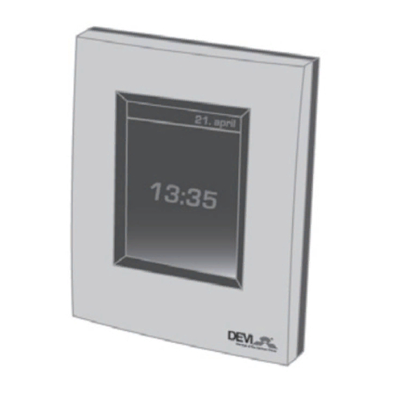
devilink™ System Overview
devilink™ is a wireless control system for underfl oor
heating. Th e central brain in the system is the devilink™ CC
(Central Controller) equipped with a colour touch screen.
From this you can control the entire heating system. Th e
devilink™ CC communicates wirelessly with all other
devilink™ units in the installation.
devilink™ FT (Floor Th ermostat) is fi tted in individual
rooms for switching the heating element on and off . It
can also have a fl oor sensor connected to measure the
temperature in the fl oor.
If you wish to measure room temperature, a devilink™ RS
(Room Sensor) can be installed. Th is has a built-in room
sensor and thus measures the ambient temperature. You can
also turn the temperature up/down via this.
devilink™ RS
Installation scenario:
devilink™ CC
devilink™ FT
2
Advertisement

Summary of Contents for Devilink eCentral-1210
- Page 1 System Overview devilink™ is a wireless control system for underfl oor heating. Th e central brain in the system is the devilink™ CC (Central Controller) equipped with a colour touch screen. From this you can control the entire heating system. Th e devilink™...
- Page 2 1. Position of devilink™ CC Not on a wall subjected to direct sunlight. Installation height should typically be between 140-170 cm. In wet rooms it should be installed on an even surface, according to local building regulations. At least 50 cm away from windows/doors that will occasionally be left open Not on the inner side of a wall facing the outside.
- Page 3 PSU (in-wall Power Supply) devilink™ NSU (Net supply) Do not power the devilink™ CC until the manual tells you to do so. Do not remove the protective fi lm on the touch screen, the end user should do this.
- Page 4 BSU. Ensure that the batteries are in the correct position. Slide the lid back on and attach the Battery Pack BSU on to the back of the devilink™ CC. When you are ready to carry out commissioning turn the switch located on the BSU to the ON position.
- Page 5 3. Confi guration of devilink™ b. When the system is powered for the fi rst time you will be met with this screen. Please select your choices c. Remove the front cover from the CC by gently pulling it off . Press and hold the install pin with a pen for 3 seconds to start the installer menu.
- Page 6 3. Confi guration of devilink™ d. Now create the rooms where the local units are installed. Add New Room: Th e Confi gure Room menu now appears. Press Room Devices and then Add a Device...
- Page 7 3. Confi guration of devilink™ Max 1.5 m Repeat until all devices in the room have been added. When you have completed adding all the devices for the room, you will get an overview of the devices associated to the room.
- Page 8 Now go back to the section 3.d. and repeat this for all rooms in the installation. Now turn off the battery pack and place the devilink™ CC on the mounting plate that you installed earlier. It will now power up again and show you a screen like this Press/select the install pin again to finalise the installation.
- Page 9 At the end of the network test you will be informed that the test is waiting for the devilink™ RS units. You have to go to all the devilink™ RS units only and press the ON/OFF button for 5 sec.
-
Page 10: Modifying An Existing Installation
4. Modifying an existing Installation 4. Modifying an existing Installation. Create new room and add device(s). See section 3.d. b. Add devices to an existing room. Go to section 4.1 Add a service device (eg. an outdoor sensor). Go to section 4.2 d. - Page 11 4. Modifying an existing Installation 4.2 Adding a service device: A service device is for instance an outdoor sensor, tariff module, power meter, etc. You should do a network test now. See section 3.e.
- Page 12 DEVI recommends that a floor sensor is always installed; temperature control is less accurate without the floor sensor. If more than one devilink™ FT’s is installed in the same room they must have the same sensor configuration. Do not use devilink™ without a floor sensor when the heating element is...
- Page 13 4. Modifying an existing Installation To change the type of regulation, go to the service menu.
- Page 14 4. Modifying an existing Installation In Heat Regulation you can change: • Forecasting method • Regulation type • Maximum floor temperature. The default setting is 35°C. To change this setting you will need to enter the pin code: 0044. Notice: The floor temperature is measured where the sensor is placed.
- Page 15 ON the safety switch and continue to hold in until the LED fl ashes red (approx. 5 sec.) devilink™ RS: Take the front cover off . Take out one battery and hold the ON/ OFF/Install button down while reinserting the battery. Continue to hold down the install button until it fl ashes (approx.
-
Page 16: Troubleshooting
5. Trouble shooting 5.1 Warnings: If an alert or warning occurs, a yellow alert icon will be shown on the Standby screen. Now press the red button, and then the View Alerts, to find more infor- mation on the issue. - Page 17 5. Trouble shooting 5.2 FAQ: Regulation type: Q: Why can’t I choose the regulation type that I want? A: Make sure the device configuration is correct, see Heat Regulation section If you need to add a floor sensor to your FT, you must uninstall the FT .When you have mounted the sensor, add the FT to the system once again.
-
Page 18: Technical Specifications
6. Technical specifi cations Installer tool battery warning Battery level Critical on device Battery level low on device Device not responding Too many dead devices Heating turned off in a room Min. fl oor temperature limit Tamper proof / Restrictions enabled Manual operation Icon for Floor Temperature Icon for Room temperature... - Page 19 NSU (Net Adapter) Operation Voltage 100-240 VAC 50/60Hz Output Voltage 15 VDC ±10% Standby power consumption Max. 0.75W Cable length. 2.5m Max load devilink™ BSU (Battery Supply Unit) Output Voltage 15 VDC ±10% Number of batteries 10 x AA...
Need help?
Do you have a question about the eCentral-1210 and is the answer not in the manual?
Questions and answers