Advertisement
8
1
5
9
7
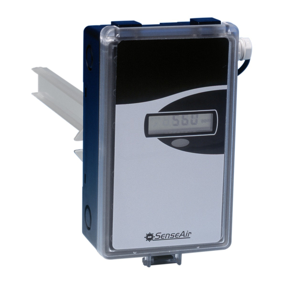
Fig. 1
1
Wall plate
2
PCB (Factory supplied
mounted in box)
3
Temperature sensor for
internal compensation (not
shown)
Installation Manual
aSENSE mIII
9
3
2
4
6
4
Carbon monoxide sensor (not shown)
5
Hole for wall plate hooks
6
Snap-in lid
7
Locking screw of the lid (not shown)
8
PG9 cable entry bushing
9
Air holes
Advertisement
Table of Contents

Subscribe to Our Youtube Channel
Related Manuals for SenseAir aSENSE mIII


Summary of Contents for SenseAir aSENSE mIII
- Page 1 Installation Manual aSENSE mIII Fig. 1 Wall plate PCB (Factory supplied Carbon monoxide sensor (not shown) mounted in box) Hole for wall plate hooks Temperature sensor for Snap-in lid internal compensation (not Locking screw of the lid (not shown) shown)
- Page 2 85 (3,35) Fig. 2 Dimensions in mm (inch) 11 Lidlocking screw 12 Wall plate 13 Screw to hold the wall plate 14 Marking to drill hole for PG7 15 Marking to drill hole for PG9 Wall Mounting Instruction Electrical cable entry. Mount the cable entry bushing in dimension PG9. Never feed more than one cable through each cable entry bushing, or else gas might leak through! Dismount the wall plate.
- Page 3 Unless different transformers are used, special precautions need to be taken. NOTE: The signal ground is not galvanically separated from the aSENSE mIII power supply! The same ground reference has to be used for the aSENSE mIII unit and for the control system! Connection Function...
- Page 4 The PCB can be removed during the making of holes. NOTE:The PCB must be handled carefully and protected from electrostatic discharge! Start-up of the aSENSE mIII Connect the power directly after mounting. The unit works best if the sensor is continuously powered.
Need help?
Do you have a question about the aSENSE mIII and is the answer not in the manual?
Questions and answers