Table of Contents
Advertisement
Quick Links
Advertisement
Table of Contents

Summary of Contents for Andover Controls xPDISPLAY
- Page 1 DISPLAY Keypad/Display Module Installation & User Guide SENSOR...
- Page 2 Andover Controls Corporation. Produced in the United States of America. Infinity is a trademark of Andover Controls Corporation. All other trademarks are the property of their respective owners. xPDISPLAY Installation & User’s Guide, Version: A July, 2003...
- Page 3 Le présent appareil numérique n’émet pas de bruits radioélectriques dépassant les limites applicables aux appareils numériques de la class A prescrites dans le Règlement sur le brouillage radioélectrique édicté par le ministère des Communications du Canada. xPDISPLAY Installation & User’s Guide...
- Page 4 Andover Controls Corporation...
-
Page 5: Table Of Contents
Contents Introduction ..............1 xPDISPLAY Features ............2 Mechanical Installation (Remote Version) .....3 Expansion Bus Connection ..........6 Pre-Operation ..............7 Keypad ................7 Setup Mode...............8 Display Configuration............9 Plain English Display Manipulation......10 Display Programming ............16 Keypad Programming............19 Troubleshooting.............21 xPDISPLAY Installation & User’s Guide... - Page 6 Andover Controls Corporation...
-
Page 7: Introduction
Cost-effective and compact, the xPDISPLAY may be mounted directly on dry wall, or any suitable electrical outlet box, and is intended for indoor use only. -
Page 8: Xpdisplay Features
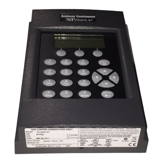
Features 16 Character x 4 Line LCD Display with LED Backlight 21-key Custom Keypad with tactile feedback 3 programmable “soft” keys Plain English software control of display backlight Internally mounted within the i2920, b3920 or b4920 case (Internal Display) -
Page 9: Mechanical Installation (Remote Version)
5. Guide the expansion cable from the controller through the opening in the back of the module. Use the internal strain relief of the electrical box or the Heyco strain relief supplied with the unit. 6. Expansion cable connection details can be found elsewhere in this manual. xPDISPLAY Installation & User’s Guide... - Page 10 8. Place the plastic cover over the module. The cover is fastened by inserting a #6 Allen tool (Andover Controls part # 30-3001-350) into the Allen fastener found at the bottom of the case as shown. Turn the screw counter-clockwise, backing it out until it is flush with the case.
- Page 11 Overall Dimensions The xPDISPLAY module is designed to be mounted flush with a wall. The overall dimensions of the module are as shown: xPDISPLAY Installation & User’s Guide...
-
Page 12: Expansion Bus Connection
A 3-foot (914mm) cable is supplied with the xP-Display product. A 10-foot (3M) cable is supplied with the xP-Display-10 product. Warning Make sure that power is not applied to the controller while you are connecting the module as the unit is not designed to be “hot-swapped”. Andover Controls Corporation... -
Page 13: Pre-Operation
Pre-Operation The xPDISPLAY module requires connection to an external controller for its power and display data. Warning: Never connect the display while power is applied to the controller. After connection, apply power. If the display has never been configured before, it should... -
Page 14: Setup Mode
Setup Mode The xPDISPLAY module includes a twenty-one-button keypad that allows you to interact with your system. The condition of each key can be interrogated via Plain English commands. However, there are some local functions that can be performed on the xPDISPLAY without the use of programming. -
Page 15: Display Configuration
The following page contains a chart indicating the setup of each of the xPDISPLAY channels. It would be best to configure your system to accommodate the xPDISPLAY according to this table before attempting to use any of its functions individually. -
Page 16: Plain English Display Manipulation
The Plain English interaction with the front panel is accomplished using a set of SystemVariables described in the table below. XPDISPLAY System Variables Function Type... - Page 17 Password This mode allows for a user to enter a password. Only numeric entries are allowed. The password entered is returned in the ACCLCDAnswerStr. 6,7,8 Setup Mode This mode displays the initial power-on screen. xPDISPLAY Installation & User’s Guide...
- Page 18 Editing functions such as automatic cursor positioning and key acceptance is performed locally by the xPDISPLAY. In this mode, the text on lines 1, 2 and 4 of the LCD display is determined by the strings ACCLCDDispLine1, ACCLCDDispLine2 and ACCLCDDispLine4.
- Page 19 Line 3 of the display contains the string set by ACCLCDDispLine 3. All 16 characters of line 3 are editable and can contain any of the xPDISPLAY alpha-numeric key entries. If no activity is detected for a brief interval, the xPDISPLAY will Auto-Accept the key entry and automatically advance the cursor.
- Page 20 European: dd/mm/yy hh:mm If the string sent in ACCLCDDispLine 3 is not in the above format, the xPDISPLAY will format the string accordingly. It expects 5 numeric fields, from left to right, separated by a delimiter. If there are less than 5 numeric fields, the remaining fields default to 0. In the case of Standard time, it scans for the first occurrence of a “pm”...
- Page 21 Only the UP ARROW, DOWN ARROW and three soft key entries are sent to the Controller in the LCDKeyStroke numeric. All other keys are used locally by the display unit for data entry and editing. xPDISPLAY Installation & User’s Guide...
-
Page 22: Display Programming
The xPDISPLAY can be used to display varying types of data. Displaying characters on the LCD requires: 1. You must set a particular mode of operation. Refer to the discussion of Display Modes found elsewhere in this manual. - Page 23 LCD Character Set The xPDISPLAY can display the following character set: Code Char Code Char Code Char Code Char Code Char Code Char “ & ‘ < > NOTE: All values are in Decimal. These values conform to standard ASCII character codes xPDISPLAY Installation &...
- Page 24 To illuminate the backlight for a set period of time, set this variable to the number of seconds desired. The resolution of this time is specified in one-second increments with 65535 seconds being the maximum. A value of zero (0) turns the backlight off. Andover Controls Corporation...
-
Page 25: Keypad Programming
English variables. There are two ways keypad information is retrieved from the xPDISPLAY. Depending upon the selected Display mode, single keystrokes or entire entries are sent. Note: If a key is held down, the xPDISPLAY will auto-repeat the key after a short delay. Data Entry... - Page 26 Enter key press is detected at the keypad. Keypad Sleep Mode If the ACCLCDBacklight variable is set to OFF, the xPDISPLAY will not transmit any Key Stroke values after a key is pressed. Pressing a key in this state turns ON the backlight for a 30-second period.
-
Page 27: Troubleshooting
Check that expansion cable is properly connected between the controller and the module. Check the view angle adjustment control (inside the cover). This may need to be adjusted for your lighting conditions. xPDISPLAY Installation & User’s Guide... - Page 28 Unit Appears Functional But Is Not Responding To Controller If the LCD is displaying normally chances are that the unit is operational. However, in that the xPDISPLAY is a programmable unit, it is possible that there is a programming problem. Try to determine the source of the problem.
- Page 29 Installation & User’s Guide...
- Page 30 30-3001-839 xPDISPLAY Installation & User’s Guide Rev A...
Need help?
Do you have a question about the xPDISPLAY and is the answer not in the manual?
Questions and answers