Table of Contents
Advertisement
Advertisement
Table of Contents

Summary of Contents for Concurrent Technologies RCIM
- Page 1 Real-Time Clock and Interrupt Module (RCIM) Userís Guide 0898007-1000 March 2021...
- Page 2 Copyright 2021 by Concurrent Real-Time. All rights reserved. This publication or any part thereof is intended for use with Concurrent Real-Time products by Concurrent Real-Time personnel, customers, and end–users. It may not be reproduced in any form without the written permission of the publisher. The information contained in this document is believed to be correct at the time of publication.
-
Page 3: Preface
Two RCIM models are described in this guide: RCIM III and RCIM IV. The use of the term “RCIM” refers to functionality common to both boards. “RCIM III” and “RCIM IV” refer to the specific boards. Refer to the section “Specifications” on page 1-3 for specifications for each of the boards. - Page 4 RCIM User’s Guide Syntax Notation The following notation is used throughout this guide: italic Books, reference cards, and items that the user must specify appear in italic type. Special terms may also appear in italic. User input appears in list bold type and must be entered exactly list bold as shown.
-
Page 5: Table Of Contents
Unpacking the RCIM........ - Page 6 RCIM IV Pin Configuration ........
-
Page 7: Chapter 1 Introduction
RCIMs, and from the RCIMs to all the associated host systems. A synchronized high-resolution clock is provided so that all the RCIMs in an RCIM chain on multiple systems can share a common time base. It also provides a local POSIX 1003.1 compliant high resolution clock. - Page 8 These functions can all generate local interrupts on the system where the RCIM card is installed. When systems are chained together, multiple input and output interrupts can be distributed to other RCIM-connected systems.
-
Page 9: Specifications
Introduction Specifications Feature RCIM IV RCIM III Clocks POSIX Length 64 bits (two 32-bit words) 64 bits (two 32-bit words) High-order 32 bits–1 second High-order 32 bits–1 second Resolution Low-order 32 bits–400 nsec Low-order 32 bits–400 nsec Oscillator stability +/-1.0 PPM +/-2.5 PPM... - Page 10 RCIM User’s Guide...
-
Page 11: Chapter 2 Hardware, Installation And Configuration
This section provides illustrations and descriptions of the RCIM IV and RCIM III boards. The RCIM boards mount into a standard PCI Express slot on a host system. A connector is mounted on each RCIM for connection to external interrupts, and a synchronization cable... - Page 12 RCIM User’s Guide RCIM IV Board Illustration Figure 2-1 shows the RCIM IV board with optional high stability OCXO (Oven Controlled Crystal Oscillator) and GPS modules installed. Figure 2-1 RCIM IV Board GPS Module GPS Module Connectors Oven Controlled Crystal...
- Page 13 External Interrupt SFP Input Connector Connector I/O Connector Connector LED Functions There are two bi-colored status LEDs near the input and output connectors on the RCIM IV board. They will both glow dimly RED when the board is in reset mode...
- Page 14 RCIM IV boards. The output cable connector is used when the RCIM is either the master or a slave in the middle of an RCIM chain (see page 2-14 for a description of RCIM modes). The input cable connector is used when the RCIM is acting in slave mode or in the middle of an RCIM chain.
- Page 15 (DIs). Each pin is physically wired to be both an input and an output with the ability to disable the output gate. If no external wire is connected to an RCIM pin, the pin can act as both an input and output simultaneously for loopback connections.
- Page 16 EXT_RXD EXT_INOUT0 RCIM IV external interrupt inputs have a selectable termination of 100 Ohms and are capable of 3.3V or 5V TTL levels. The recommended input signal duration is 1us and because termination can be disabled there is no minimum amperage requirement for line drivers.
-
Page 17: Rcim Iv
Polling is done continuously and messages that report the status of the RCIM IV daisy chain cables are output when an error condition is detected. Messages indicating problems will appear on the systems directly connected by a failing link. -
Page 18: Board Illustration
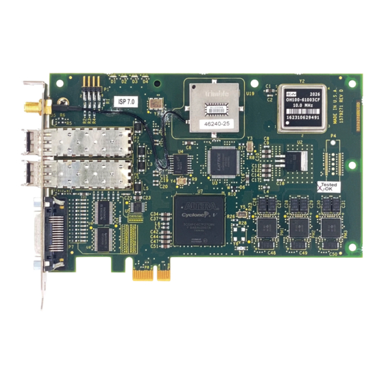
Refer to Chapter 3 for instructions for synchronizing clocks. RCIM III Board Illustration Figure 2-4 shows the RCIM III board with optional high stability OCXO (Oven Controlled Crystal Oscillator) and GPS modules installed. Figure 2-4 RCIM III Board... -
Page 19: Connectors And Leds
SFP Output SFP Input Connector I/O Connector Connector Connector LED Functions There are two bi-colored status LEDs near the input and output connectors on the RCIM III board. They will both glow dimly RED when the board is in reset mode... -
Page 20: Oscillators
RCIM III boards. The output cable connector is used when the RCIM is either the master or a slave in the middle of an RCIM chain (see page 2-14 for a description of RCIM modes). The input cable connector is used when the RCIM is acting in slave mode or in the middle of an RCIM chain. -
Page 21: Gps Antenna
Hardware, Installation and Configuration GPS Antenna The GPS option on the RCIM III includes an active GPS antenna and coaxial cable. The antenna receives the GPS satellite signals and passes them to the receiver. The GPS signals are spread spectrum signals in the 1575 MHz range and do not penetrate conductive or opaque surfaces. - Page 22 RCIM User’s Guide Figure 2-6 RCIM III External Interrupt I/O Connector Pin-outs EXT_INT0 EXT_PIG0 EXT_INT1 EXT_PIG1 EXT_INT2 EXT_PIG2 EXT_INT3 EXT_PIG3 EXT_INT4 EXT_PIG4 EXT_INT5 EXT_PIG5 EXT_INT6 EXT_PIG6 EXT_INT7 EXT_PIG7 EXT_INT8 EXT_PIG8 EXT_INT9 EXT_PIG9 EXT_INT10 EXT_PIG10 EXT_INT11 EXT_PIG11 EXT_CLKIN EXT_CLKOUT EXT_RXD1 EXT_TXD1...
-
Page 23: System Identification
EXT_CLKIN EXT_CLKOUT external clock driving the RCIM III should be capable of driving a 5V TTL signal into a 50 ohm load. The RCIM III will automatically switch to using the external clock if one is present. The external clock output from the RCIM III is driven using a... -
Page 24: Connection Modes
RCIM III and RCIM IV boards. If your system will be part of an RCIM chain, it is best to determine the desired connection mode before installing an RCIM; it is easier to connect the optical cable to the cable connectors before the RCIM is installed. -
Page 25: Unpacking The Rcim
This information is provided for those cases where an RCIM is added to a system in a post-manufacturing environment. In order to successfully install the RCIM, you must know if you will be using the RCIM to accept or deliver external interrupts and the mode in which the RCIM will run (isolated, master, pass-through slave or final slave). -
Page 26: Configuration
4. Install the RCIM into the desired slot, securing the card in the slot using the mechanism provided by the case. 5. If this is to be part of an RCIM chain, attach the cable as required. See the section “Connection Modes” to determine how to connect the cable based on the connection mode for this system. -
Page 27: Driver Configuration
Create associations between internally generated interrupt signals, output lines and distributed-interrupt lines. • Set the name of the system in an RCIM chain that has the master RCIM. • Decide whether the tick and POSIX clock is to be driven by the local RCIM oscillator or by the master RCIM oscillator, for RCIMs that are in an RCIM chain. -
Page 28: General Considerations
MSI Interrupt Configuration RCIM IV and the latest versions of RCIM III (revision 9 and later) support MSI (message signaled interrupts). By default, the RCIM kernel driver will initialize the hardware to use MSI interrupts instead of PCI INTA interrupts whenever possible. By using MSI interrupts, the RCIM is guaranteed of having its own non-shared interrupt, thus providing more reliable interrupt response times. -
Page 29: System Timekeeping Configuration For Gps Support
Hardware, Installation and Configuration For a statically linked RCIM driver, this tunable can be specified on the GRUB boot loader command line (rcim.nomsi=1). For an RCIM in module form, this tunable can be placed in /etc/modprobe.conf as “options rcim.nomsi=1”. System Timekeeping Configuration for GPS Support If your system contains the optional GPS module, system timekeeping daemons must be installed and configured to use the GPS receiver to synchronize the RCIM’s POSIX clock... - Page 30 GENERIC(0) is the GPS attached to the RCIM. The other lines are time servers assigned by pool.ntp.org. The first column indicates which servers are being selected for synchronization. The '*' in front of GENERIC(0) indicates that the RCIM GPS receiver is being used as the system peer.
- Page 31 Hardware, Installation and Configuration in view: 18, 26, 29", trimble_tracking_status[10]="ch=0, acq=ACQ, eph=3, signal_level= 2.60, elevation= 18.18, azimuth= 86.56, collecting data", trimble_tracking_status[18]="ch=1, acq=ACQ, eph=19, signal_level= 5.20, elevation= 39.47, azimuth= 289.19, collecting data", trimble_tracking_status[26]="ch=2, acq=ACQ, eph=19, signal_level= 15.40, elevation= 69.34, azimuth= 49.55, collecting data", trimble_tracking_status[29]="ch=3, acq=ACQ, eph=19, signal_level= 15.80, elevation= 52.49, azimuth= 48.45, collecting data", trimble_receiver_health="doing position fixes, Battery backup failed",...
- Page 32 RCIM User’s Guide...
-
Page 33: Chapter 3 Functional Description
The Real-Time Clock and Interrupt Module (RCIM) provides two non-interrupting clocks. One of these clocks can be synchronized with all the RCIMs in an RCIM chain to provide a common time stamp across systems. The other clock is POSIX 1003.1 compliant and, although not synchronized across the RCIM chain, it increments in unison with the other clock on the RCIM board and can be set to a specific time. -
Page 34: The Tick Clock
When an RCIM board is part of an RCIM chain, the tick clocks on all slave RCIMs are incremented and cleared in synchronization with whatever incrementing and clearing is done to the tick clock located on the master RCIM. -
Page 35: Direct Access To The Clocks
The device file /dev/rcim:N/sclk (where N is the RCIM card number starting from zero) can be used to access the RCIM clocks directly using mmap(2). From the address returned by mmap, the following offsets are used to access the clock fields:... - Page 36 ENABLED/DISABLED – For the RCIM master, indicates if the cable clock signal is being propagated to slaves. For RCIM slaves, indicates if clocks are being driven by the RCIM master or if ticking locally (without synchronization).
-
Page 37: Synchronizing The Tick Clock
Status: is one of the following: tick timer CABLE_SYNC – indicates that the RCIM slave clock is being driven by RCIM master cable clock signal, if posix clock available CABLE_ENABLE – indicates that the RCIM clock resets when RCIM master does a synchronization LOCAL_ENABLE –... -
Page 38: Automatic Synchronization
The system can also be configured to automatically synchronize the tick clocks when an RCIM slave system is booted. This feature is disabled by default and should be used with caution. It causes the tick clock on all systems to be reset to zero when any system in the RCIM chain is booted, which may have an undesirable impact on processes using the tick clock during synchronization. - Page 39 GPS receiver. This symbolic link is pointed to the last RCIM found with a GPS. If another RCIM is to be used, the administrator must point this special device to the uart special device file of the desired RCIM to, for example, /dev/rcim:3/uart.
-
Page 40: Interrupt Processing
RCIM User’s Guide Interrupt Processing One or more of the following modules is used for interrupt processing on the RCIM: • Edge-Triggered Interrupts (ETIs) – An ETI allows you to use an external event to trigger an interrupt. Documentation for ETIs begins on page 3-12. -
Page 41: Arming And Enabling Dis And Etis
RCIM board is attached, and additionally to other systems in the RCIM chain if configured to do so. The ETI or DI interrupt handler on the host clears the pending bit each time it concludes the processing of an interrupt. This clears the way for the RCIM board to output the next instance of this interrupt. -
Page 42: Setting Up Distributed Interrupts
RCIM User’s Guide Setting up Distributed Interrupts The RCIM provides the ability to share interrupts across interconnected systems using an RCIM chain. Although distributed interrupts are covered in detail starting on page 3-17, the figures below provide an illustration of how they operate. Guidelines for setting up distributed interrupts based on the illustration follow. -
Page 43: Obtaining Rcim Values
RCIM_GET_INFO RCIM_GET_ADDR rcim(4) man page. mmap(2) system call: mmap can be used to map in some or all of the device registers of the RCIM board. The register layout is in /usr/include/linux/rcim_ctl.h and in Appendix B in this guide. 3-11... -
Page 44: Edge-Triggered Interrupts
1 to trigger on the rising edge of its input signal input2/h sets input 2 to trigger on a high signal value See the “Configuration” section in Chapter 2 or the rcim(4) man page for the various methods available for specifying configuration options. 3-12... -
Page 45: Eti Device Files
Each ETI is accessed through its own special device file: /dev/rcim:N/etiM where N is the RCIM card number (starting from zero) and M is the ID of the ETI. These files are created automatically on system boot by the /etc/init.d/rcim initialization script. -
Page 46: Distributed Etis
RCIM User’s Guide Distributed ETIs Any or all of the ETIs on an RCIM can be distributed to all systems connected by an RCIM chain. The source of a distributed ETI can be located on any of the RCIMs in the chain. -
Page 47: User Interface To Rtcs
RTC generates an interrupt IOCTLSIGATTACH External Output Interrupts Each RCIM provides external output signals. These signals can be used as interrupt sources for other machines or used as signals to control external devices. RCIMs can support up to twelve external output interrupts (0-11). -
Page 48: Output Source Configuration
Note that on the RCIM IV each EXT_INOUT pin needs to first be configured as an output line before it can be driven with a source. See “RCIM IV Pin Configuration” on page 3-20 for more information. -
Page 49: Pig Device File
If the signal is being fed into an RCIM IV, it must hold any low or high value for at least 1 microsecond before changing to the next state. For an RCIM III the duration held must be 1.5 microseconds. -
Page 50: Di Configuration
RCIM User’s Guide can also be configured and used locally on an isolated system. Configuration details are given in the “DI Configuration” section below. See the section “Obtaining RCIM Values” on page 3-11 for the methods available for obtaining configuration information. -
Page 51: Di Device Files
Each distributed interrupt is accessed through its own special device file: /dev/rcim:N/diM where N is the RCIM card number (starting from zero) and M is the ID of the distributed interrupt. These files are created automatically on system boot by the /etc/init.d/rcim initialization script. -
Page 52: Rcim Iv Pin Configuration
RCIM User’s Guide RCIM IV Pin Configuration Unique to the RCIM IV, each of the EXT_INOUT pins can be configured to be either input or output, as well as terminated or non-terminated. pinN/[out|in]/[non-terminated|terminated] The flag words (out, in, non-terminated, terminated) can be specified using the first character of the word. -
Page 53: Rcim Iv Address Map
RCIM IV Registers Appendix A This section contains the address map and registers on the RCIM IV board. Note that some registers appear at two places in the physical address space. For these registers there is an associated Xregister. For example PCSAT and XPCSAT. The Xregister accommodates systems with a 64k, rather than the old 4k page size. - Page 54 RCIM User’s Guide Address Function 0xXXX00400 Clear Cable Errors Register (Write Only) 0xXXX00410 Output Cable Status Register (Read Only) 0xXXX00420 Input Cable Status Register (Read Only) 0xXXX01000 Tick Clock Upper Register 0xXXX10000 Tick Clock Upper Register 0xXXX01008 Tick Clock Lower Register...
- Page 55 RCIM IV Registers Address Function 0xXXX03010 Programmable INTR Generator Set Register (Write Only) 0xXXX30010 Programmable INTR Generator Set Register (Write Only) 0xXXX03020 Programmable INTR Generator Clear Register (Write Only) 0xXXX30020 Programmable INTR Generator Clear Register (Write Only) 0xXXX03040 External I/O Output Enable Register...
- Page 56 RCIM User’s Guide Address Function 0xXXX06090 IRIG Output Years Register 0xXXX06094 IRIG Output Control Bits Register 0xXXX06098 IRIG Output SBS Register 0xXXX06100 IRIG ADC Data Register (Read Only) 0xXXX06110- IRIG ADC History Registers (Read Only) 0xXXX0614C 0xXXX06160 IRIG DAC Data Register...
-
Page 57: Rcim Iv Registers
RCIM IV registers are illustrated in this section. NOTE: Unless otherwise stated, a bit value of 1=on; 0=off Figure A-1 RCIM IV Board Status/Control Register This register provides status and control of certain features of the RCIM IV board. Offset: 0x00000 Bits... - Page 58 RCIM User’s Guide Figure A-2 RCIM IV Firmware Revision/Options Present Register This register provides information on what options are present on this RCIM board and the firmware revision. Offset: 00004 Bits 31 30 29 28 27 26 25 24 23 22 21 20 19 18 17 16 15 14 13 12 11 10 9...
- Page 59 Figure A-3 RCIM IV Board Identity Register Setting bit 7 causes the RCIM LEDs to flash red and green once per second to identify the specific board, useful when there are multiple RCIMs in a one system. Clearing bit 7 will resume normal operation.
- Page 60 RCIM User’s Guide Figure A-4 RCIM IV Interrupt Enable/Request/Pending/Clear/Arm/Level/Polarity Registers The enable registers enable the selected interrupts. The request registers are software driven requests of the selected interrupts. The pending registers are pending requests. The clear registers clear the selected interrupts.
- Page 61 RCIM IV Registers Figure A-5 RCIM IV External Interrupt Routing Registers The external interrupt routing registers route selected interrupts to the external interrupt connector. Offset: 00070, 00074, 00078 External Interrupt Number Register Number Bits 31 30 29 28 27 26 25 24 23 22 21 20 19 18 17 16 15 14 13 12 11 10 9 8 7 6 5 4 3 2 1 0 Res.
- Page 62 RCIM User’s Guide Figure A-6 RCIM IV Cable Interrupt Routing Registers The cable interrupt routing registers route selected interrupts to the RCIM interconnecting cable. Offsets: 00080, 00084, 00088 Cable Interrupt Number Cable Interrupt Register 1 Bits 31 30 29 28 27 26 25 24 23 22 21 20 19 18 17 16 15 14 13 12 11 10 9 8 7 6 5 4 3 2 1 0...
- Page 63 31 30 29 28 27 26 25 24 23 22 21 20 19 18 17 16 15 14 13 12 11 10 9 8 7 6 5 4 3 2 1 0 GPS PPS Snapshot Figure A-8 RCIM IV GPS PPS Seconds Snapshot Register The GPS PPS Seconds Snapshot register contains a snapshot of the seconds field of the POSIX clock. The snapshot is taken every time the GPS PPS signal occurs.
- Page 64 31 30 29 28 27 26 25 24 23 22 21 20 19 18 17 16 15 14 13 12 11 10 9 8 7 6 5 4 3 2 1 0 Cable Snapshot Figure A-10 RCIM IV Cable Seconds Snapshot Register The Cable Seconds Snapshot register contains a snapshot of the seconds field of the POSIX clock. The snapshot is taken every time the cable master time is received.
- Page 65 31 30 29 28 27 26 25 24 23 22 21 20 19 18 17 16 15 14 13 12 11 10 9 8 7 6 5 4 3 2 1 0 IRIG PPS Snapshot Figure A-12 RCIM IV IRIG PPS Seconds Snapshot Register The IRIG PPS Seconds Snapshot register contains a snapshot of the seconds field of the POSIX clock. The snapshot is taken every time the IRIG PPS signal occurs.
- Page 66 RCIM User’s Guide Figure A-13 RCIM IV Cable Master Time Register The Cable Master Time register contains the seconds field of the master RCIM POSIX clock that is transmitted on the cable at every transition of the clock at the seconds boundary.
- Page 67 RCIM IV Registers Figure A-14 RCIM IV Clear Cable Errors Register This is a Write Only register that clears any reported cable errors. The data field is don’t care. Offset: 00400 Bits 31 30 29 28 27 26 25 24 23 22 21 20 19 18 17 16 15 14 13 12 11 10 9 8 7 6 5 4 3 2 1 0...
- Page 68 RCIM User’s Guide Figure A-16 RCIM IV Input Cable Status Register This register provides detailed hardware status information pertaining to the input cable. Offset: 00420 Bits 31 30 29 28 27 26 25 24 23 22 21 20 19 18 17 16 15 14 13 12 11 10 9...
- Page 69 RCIM IV Registers Figure A-18 RCIM IV Tick Clock Lower Register This register contains the lower 32 bits of the tick clock. Offsets: 01008, 10008 Bits 31 30 29 28 27 26 25 24 23 22 21 20 19 18 17 16 15 14 13 12 11 10 9 8 7 6 5 4 3 2 1 0...
- Page 70 RCIM User’s Guide Figure A-20 RCIM IV POSIX Clock Seconds Register This register contains the POSIX clock seconds. Offsets: 01100, 10100 Bits 31 30 29 28 27 26 25 24 23 22 21 20 19 18 17 16 15 14 13 12 11 10 9 8 7 6 5 4 3 2 1 0...
- Page 71 Cable Enable (R) Local Enable (R/W) Select Cable Enable (R/W) Select Cable Clock (R/W) Figure A-23 RCIM IV POSIX Clock Skip/Add Time Register This register skips/adds time to the POSIX clock in 400 nanosecond increments. Offsets: 01114, 10114 Bits 31 30 29 28 27 26 25 24 23 22 21 20 19 18 17 16 15 14 13 12 11 10 9 8 7 6 5 4 3 2 1 0...
- Page 72 The initial RTC timer value is loaded in the RTC timer registers. The current value of the timer is read from this register. NOTE: Loading this register also loads the RTC Repeat Register for compatibility with RCIM. Offsets: 02010, 02030, 02050, 02070, 02090, 020B0, 020D0, 020F0...
- Page 73 RCIM IV Registers Figure A-27 RCIM IV RTC Control Registers This register provides control of the RTCs. Offsets: 02000, 02020, 02040, 02060, 02080, 020A0, 020C0, 020E0 Bits 31 30 29 28 27 26 25 24 23 22 21 20 19 18 17 16 15 14 13 12 11 10 9 8 7 6 5 4 3 2 1 0 Res.
- Page 74 31 30 29 28 27 26 25 24 23 22 21 20 19 18 17 16 15 14 13 12 11 10 9 8 7 6 5 4 3 2 1 0 Reserved Figure A-29 RCIM IV Programmable Interrupt Set and Clear Registers Writing to these registers sets/clears the unitary bits in the Programmable Interrupt Register without affecting the other bits.
- Page 75 31 30 29 28 27 26 25 24 23 22 21 20 19 18 17 16 15 14 13 12 11 10 9 8 7 6 5 4 3 2 1 0 Reserved External I/O Output Enable Figure A-31 RCIM IV External I/O Output Enable Set/Clear Registers Writing to these registers sets/clears the unitary bits in the external I/O output enable register without affecting the other bits.
- Page 76 31 30 29 28 27 26 25 24 23 22 21 20 19 18 17 16 15 14 13 12 11 10 9 8 7 6 5 4 3 2 1 0 Reserved External I/O Terminator On Figure A-33 RCIM IV External I/O Terminator On Set/Clear Registers Writing to these registers sets/clears the unitary bits in the external I/O terminator on register without affecting the other bits.
- Page 77 RCIM IV Registers Figure A-34 RCIM IV GPS Receive Pointers The GPS receive pointers are used for communication with the optional GPS module. Offset: 03200 Bits 31 30 29 28 27 26 25 24 23 22 21 20 19 18 17 16 15 14 13 12 11 10 9...
- Page 78 RCIM User’s Guide Figure A-36 RCIM IV GPS Debug Control/Status Register The GPS debug control/status register contains bits used during testing and debug. Setting any of these bits will disable RCIM communication with the GPS module. Offset: 03208 Bits 31 30 29 28 27 26 25 24 23 22 21 20 19 18 17 16 15 14 13 12 11 10 9...
- Page 79 RCIM IV Registers Figure A-38 RCIM IV GPS Receive Data Buffer This is the GPS receive data buffer. Offset: 04000 to 047FF Bits 31 30 29 28 27 26 25 24 23 22 21 20 19 18 17 16 15 14 13 12 11 10 9 8 7 6 5 4 3 2 1 0...
- Page 80 RCIM User’s Guide A-28...
-
Page 81: Rcim Iii Address Map
RCIM III Registers Appendix B This section contains the address map and registers on the RCIM III board. Note that some registers appear at two places in the physical address space. For these registers there is an associated Xregister. For example PCSAT and XPCSAT. The Xregister accommodates systems with a 64k, rather than the old 4k page size. - Page 82 RCIM User’s Guide Address Function 0xXXX01010 Tick Clock Status/Control 0xXXX10010 Tick Clock Status/Control 0xXXX01100 POSIX Clock Seconds 0xXXX10100 POSIX Clock Seconds 0xXXX01108 POSIX Clock Nanoseconds 0xXXX10108 POSIX Clock Nanoseconds 0xXXX01110 POSIX Clock Status/Control 0xXXX10110 POSIX Clock Status/Control 0xXXX01114 POSIX Clock Skip/Add Time...
-
Page 83: Rcim Iii Registers
RCIM III Registers Address Function 0xXXX0320C GPS Communication Error Register 0xXXX03800- SPI Data Buffer 0xXXX03FFF 0xXXX04000- GPS Receive Data Buffer 0xXXX047FF 0xXXX04800- GPS Transmit Data Buffer 0xXXX04FFF... - Page 84 RCIM III registers are illustrated in this section. NOTE: Unless otherwise stated, a bit value of 1=on; 0=off Figure B-1 RCIM III Board Status/Control Register This register provides status and control of certain features of the RCIM III board. Offset: 00000 Bits...
- Page 85 RCIM III Registers Figure B-2 RCIM III Firmware Revision/Options Present Register This register provides information on what options are present on this RCIM board and the firmware revision. Offset: 000004 Bits 31 30 29 28 27 26 25 24 23 22 21 20 19 18 17 16 15 14 13 12 11 10 9...
- Page 86 RCIM User’s Guide Figure B-3 RCIM III Interrupt Enable/Request/Pending/Clear/Arm/Level/Polarity Registers The enable registers enable the selected interrupts. The request registers are software driven requests of the selected interrupts. The pending registers are pending requests. The clear registers clear the selected interrupts.
- Page 87 RCIM III Registers Figure B-4 RCIM III External Interrupt Routing Registers The external interrupt routing registers route selected interrupts to the external interrupt connector. Offset: 00070, 00074, 00078 External Interrupt Number Register Number Bits 31 30 29 28 27 26 25 24 23 22 21 20 19 18 17 16 15 14 13 12 11 10 9 8 7 6 5 4 3 2 1 0 Res.
- Page 88 RCIM User’s Guide Figure B-5 RCIM III Cable Interrupt Routing Registers The cable interrupt routing registers route selected interrupts to the RCIM interconnecting cable. Offsets: 00080, 00084, 00088 Cable Interrupt Number Cable Interrupt Register 1 Bits 31 30 29 28 27 26 25 24 23 22 21 20 19 18 17 16 15 14 13 12 11 10 9 8 7 6 5 4 3 2 1 0...
- Page 89 Cable Snapshot Figure B-8 RCIM III Cable Master Time Register The Cable Master Time register contains the seconds field of the master RCIM POSIX clock that is transmitted on the cable at every transition of the clock at the seconds boundary.
- Page 90 RCIM User’s Guide Figure B-9 RCIM III Clear Cable Errors Register This is a Write Only register that clears any reported cable errors. The data field is don’t care. Offset: 00400 Bits 31 30 29 28 27 26 25 24 23 22 21 20 19 18 17 16 15 14 13 12 11 10 9 8 7 6 5 4 3 2 1 0...
- Page 91 RCIM III Registers Figure B-11 RCIM III Input Cable Status Register This register provides detailed hardware status information pertaining to the input cable. Offset: 00420 Bits 31 30 29 28 27 26 25 24 23 22 21 20 19 18 17 16 15 14 13 12 11 10 9...
- Page 92 RCIM User’s Guide Figure B-13 RCIM III Tick Clock Lower Register This register contains the lower 32 bits of the tick clock. Offsets: 01008, 10008 Bits 31 30 29 28 27 26 25 24 23 22 21 20 19 18 17 16 15 14 13 12 11 10 9 8 7 6 5 4 3 2 1 0...
- Page 93 RCIM III Registers Figure B-15 RCIM III POSIX Clock Seconds Register This register contains the POSIX clock seconds. Offsets: 01100, 10100 Bits 31 30 29 28 27 26 25 24 23 22 21 20 19 18 17 16 15 14 13 12 11 10 9 8 7 6 5 4 3 2 1 0...
- Page 94 Cable Enable (R) Local Enable (R/W) Select Cable Enable (R/W) Select Cable Clock (R/W) Figure B-18 RCIM III POSIX Clock Skip/Add Time Register This register skips/adds time to the POSIX clock in 400 nanosecond increments. Offsets: 01114, 10114 Bits 31 30 29 28 27 26 25 24 23 22 21 20 19 18 17 16 15 14 13 12 11 10 9 8 7 6 5 4 3 2 1 0...
- Page 95 The initial RTC timer value is loaded in the RTC timer registers. The current value of the timer is read from this register. NOTE: Loading this register also loads the RTC Repeat Register for compatibility with RCIM. Offsets: 02010, 02030, 02050, 02070, 02090, 020B0, 020D0, 020F0...
- Page 96 RCIM User’s Guide Figure B-22 RCIM III RTC Control Registers This register provides control of the RTCs. Offsets: 02000, 02020, 02040, 02060, 02080, 020A0, 020C0, 020E0 Bits 31 30 29 28 27 26 25 24 23 22 21 20 19 18 17 16 15 14 13 12 11 10 9 8 7 6 5 4 3 2 1 0 Res.
- Page 97 31 30 29 28 27 26 25 24 23 22 21 20 19 18 17 16 15 14 13 12 11 10 9 8 7 6 5 4 3 2 1 0 Reserved Figure B-24 RCIM III Programmable Interrupt Set and Clear Registers Writing to these registers sets/clears the unitary bits in the Programmable Interrupt Register without affecting the other bits.
- Page 98 RCIM User’s Guide Figure B-25 RCIM III GPS Receive Pointers The GPS receive pointers are used for communication with the optional GPS module. Offset: 03200 Bits 31 30 29 28 27 26 25 24 23 22 21 20 19 18 17 16 15 14 13 12 11 10 9...
- Page 99 RCIM III Registers Figure B-27 RCIM III GPS Debug Control Register The GPS debug control register contains bits used during testing and debug. Setting any of these bits will disable RCIM communication with the GPS module. Offset: 03208 Bits 31 30 29 28 27 26 25 24 23 22 21 20 19 18 17 16 15 14 13 12 11 10 9...
- Page 100 RCIM User’s Guide Figure B-29 RCIM III GPS Receive Data Buffer This is the GPS receive data buffer. Offset: 04000 to 047FF Bits 31 30 29 28 27 26 25 24 23 22 21 20 19 18 17 16 15 14 13 12 11 10 9 8 7 6 5 4 3 2 1 0...
-
Page 101: Appendix C Calculating Rcim Cable Propagation Delays
The user just needs to be aware of the delays associated with each RCIM and cable in a chain to determine if the level of clock skew is acceptable for the application. - Page 102 RCIM User’s Guide...
Need help?
Do you have a question about the RCIM and is the answer not in the manual?
Questions and answers