Advertisement
Quick Links
No. 006143
GB - Instruction
General Information
Jamara e.K. is not liable for any damage caused to the product itself or through this, provided this
is due to improper operation or handling errors. The Customer alone bears the full responsibility for
the proper use and handling, including without limitation, the assembly, the charging process, the
use and choice of the operation area. Please refer to the operating and user instructions, it contains
important information and warnings.
This model is not a toy!
Suitable for people over 14 year.
Warning:
Not suitable for children under 36 months. RISK OF SUFFOCATION.
Contains small parts which can be swallowed. Keep away necessarily from children
Box contents:
• Modell • Wheels • Undercarriage • Accessories • Instructions/Planes
Functions:
• Aileron • Elevator • Vertical fin • Throttle
Highlights:
• Fuselage made of balsa and plywood • Wings made of wood in rib construction
• Wooden construction kit • Ideal to have with you at all times • Laser cut kit
TOP MAIN WING ASSEMBLY
Recommendation: Try to find a flat surface planking (L:1200 mm; w:400mm) or glass as working table for the following steps.
Place the W3 and W2 on the working table and the slot part
upward.
Try to find the 2 pieces of W11 and one piece of W12 from the
laser-cutting parts bag and place them on the working table.
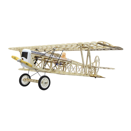
Fokker DVII
Attention!
In some countries it is a legal requirement to carry third party indemnity insurance when operating
a radio controlled model. Please ask your local dealer, governing body or your insurance company
for details.
Recommended accessories
Electric motor
Propeller AEJ
Servo
Technical data:
• Wing span: ~ 1200 mm • Length: ~ 990 mm
• Wing area ~ 41 qdm • Weight: ~ 1400 g • Servos: 4 x 13,6 g
• Battery LiPo 14,8 V 2200 mAh • Motor 1000 KV 550 W
No responsibility is taken for the correctness of this information. Subject to change without prior
notice. Errors and omissions excepted
Try to place the 3mm wide of W3 on the bottom of the W2. Use
triangle ruler when apply instant glue to secure the W3 on the
W2.
Apply UHU glue to secure the W11 on both sides of W12. Use
clip to hold them together until the glue is dried enough. Make
sure the combination remain aligned. Drop some instant glue on
the edges. Repeat the same steps for another combination.
A2820/6
No. 13 2820
10 x 7
No. 34 0124
High End 929 HMG
No. 07 4420
Close view after glue. The slot part must be upward. The angle
between W2 and W3 is 90 degree.
Refer to the assemble drawing; try to fit the W2 and W4. Don't
apply any glue on them. Try to fit the W15 and drop very small
amount of instant glue on the joint place. Fit the rib W6 from
the center part. Fit other ribs W7, W8, W8, W7, W9, W10, W12,
W13, W14 in order.
Advertisement

Related Manuals for Jamara Fokker DVII


Summary of Contents for Jamara Fokker DVII
- Page 1 General Information Attention! Jamara e.K. is not liable for any damage caused to the product itself or through this, provided this In some countries it is a legal requirement to carry third party indemnity insurance when operating is due to improper operation or handling errors. The Customer alone bears the full responsibility for a radio controlled model.
- Page 2 TOP MAIN WING ASSEMBLY Try to fit the 5 mm dowel as the leading edge. Use triangle ruler Try to fit the W3 on the main wing as the middle edge. When satisfy the location; place some heavy thing (1 KG) on when drop instant glue to secure the dowel on the W5.
- Page 3 TOP MAIN WING ASSEMBLY Try to fit the W20 on the main wing (near the leading edge); and Place W22 on working table. Try to fit the W22 on the main wing as servo tray. Press the W22 fit the W21 on the main wing near the rear edge. Press them into into the slots and drop some instant glue to secure it in place.
- Page 4 BOTTOM MAIN WING ASSEMBLY Top view of both MW9 combinations. Place MW2, MW9 combinations and MW4 on the working table. Try to fit the MW9 combinations onto the MW2 and MW4 like the picture shown. Left MW9 combination must be on the left side. Don‘t use any glue.
- Page 5 BOTTOM MAIN WING ASSEMBLY Make sure the alignment of ribs on the W5; press the ribs into Place MW13 and MW14 on the working table. Fit the MW13 to the main wing as the wing tip. Fit the MW14 into its relative slots on the MW5.
-
Page 6: Elevator Assembly
LANDING GEAR SUB WING ASSEMBLY Make sure the alignment of every ribs and every angle must be Place DW4 on the working table. Try to fit DW4 to the bottom of the sub wing as the rear edge. 90 degree; use instant glue to secure the joint places. Spread Drop some instant glue to secure it in place. -
Page 7: Rudder Assembly
ELEVATOR ASSEMBLY Try to fit the H6 into the slots on the H2; fit H7 into the slots on Use wooden planning tool to trim the tips into V shape on H2 Close view of the V shape on the tip. It is also workable to use the H3. - Page 8 RUDDER ASSEMBLY Use sanding paper to trim the top edge into round edge. Place V2, V3, V4, V5, H5 on the working table for assembling Close view of the round edge. elevator. Try to fit V4 into V2; fit H5 and V5 into V3. Use instant glue to Use wooden planning tool to trim the leading edge of the V3 into Close view of the V shape.
-
Page 9: Fuselage Assembly
RUDDER ASSEMBLY Try to fit the V1 into the rudder for marking the hinge location on V1. Use hobby knife to cut the hinge hole on V1. Wait for applying film. FUSELAGE ASSEMBLY Place F6 and F7 on the working table. Use glue to secure the F6 and F7 together. - Page 10 FUSELAGE ASSEMBLY Close view of the small recess marking on the F6 and F16. Try to fit the F5 on the F16, before the F6. Make sure the angle Use instant glue to secure the F5 in place. between F16 and F5 is 90 degree. Place F1R, F1L, F2R, F2L, F15, F3 (2pieces) and F4 (2 pieces) Use glue to secure the F1R on the F2R and secure F1L on the Place F17A o the side board;...
- Page 11 FUSELAGE ASSEMBLY Use instant glue to secure the contacting places. Make sure the alignment of both side boards on the tail. Rear view of the tail fuselage; make sure it is bilateral symmetry. Place F3, F17 and F18 on the working table. Try to fit the F28 onto the fuselage and drop some instant glue Try to fit the F19 onto the fuselage and drop some instant glue to secure it in place.
- Page 12 FUSELAGE ASSEMBLY Use glue to secure F23 inside the F6 (firewall) for reinforcement. Move the F23 to the top and make sure the reinforcement is Use glue to secure the F24 inside for reinforcing the gear mount. strong enough. It is also workable to use AB glue for securing, but it will add some weight and won‘t allow any mistake during gluing.
-
Page 13: Canopy Assembly
FUSELAGE ASSEMBLY After applying the covering on the top and sides of the fuselage; The elevator rod tubing will go through the center hole on the F9. Use hobby knife to cut hole on the right side of tail for exit the insert the rod tubing (for elevator rod) through the fuselage and rudder rod tubing. - Page 14 CANOPY ASSEMBLY Make sure the alignment of the edges and place some heavy Spread glue on the main construction. Place the main construction onto the canopy. thing on top of it. Wait for the glue dried enough Try to find 3 pieces of preserving markings on the canopy. Use There are 2 pieces of recess next to the pilot seat.
- Page 15 CANOPY ASSEMBLY Place the vacuum formed engine on the canopy and use 2.6 x Place the machine gun decal, F38 plastic tube, F39 balsa barrel, Completion of the canopy. 8mm tapping screws to secure it in place. and F40 combinations on the working table. Insert the F38 into the F39 barrel.
- Page 18 Covering and complete the model Press the edges of the decal toward the hinge and makes it flat. Place the ruler on the conjunction of the main wing and aileron. Remove the aileron and insert the hinges into the slots. Use hobby knife to cut the decal and makes the aileron separate from the main wing.
- Page 19 COVERING AND FINISHING THE MODEL Try to find the pre-serving holes on the main wing for servo, for Use soldering to melt out the covering over these holes. Drop Place the bottom wing and wing reinforcement on the working cable exit, for screw and for horn as the picture shown. small instant glue on screw holes for reinforcement.
- Page 20 COVERING AND FINISHING THE MODEL Use soldering to melt out the covering over the slots. Place the horizontal on the working table.Try to find the holes on Use soldering to melt out the covering over the holes (2mm). the elevator as the picture shown. Try to find the hole on the side of rudder (below the second hin- Use soldering to melt out the covering over the hole (2mm).
- Page 21 COVERING AND FINISHING THE MODEL Use ironer to trim the edges of the slots. Place the fuselage, 2 pieces of main gear, sub wing, 4 pieces of Try to fit the main gears into the slots; place plastic plates over plastic plates, 8 pieces of 2.6x8mm tapping screws, DW9 gauge the gear and secure the gear in place with 2.6x8mm tapping and rubber band on the working table for installing main gear.
- Page 22 COVERING AND FINISHING THE MODEL Remove the vertical. Use hobby knife to remove the covering Fit the vertical on the horizontal again. Use a triangle rule as a Try to fit the tail wing into the fuselage. The vertical must be fitted guide for making sure the angle is 90 degree and secures the into the slot on the tail of the fuselage.
- Page 23 COVERING AND FINISHING THE MODEL Take tail wheel, 2mm collar and M3x4 hex screw out of hardware Attach the clevises onto their respective horns on the elevator Keep the distance between the end of the tubing and the end of rod around 15mm; us instant glue to secure the tubing on the bag.
- Page 24 COVERING AND FINISHING THE MODEL Place the FRP cowl and venting net on the working table. Try to fit the venting net onto the FRP cowl. Fold the bending part Try to press the venting net onto the cowl until the glue dried if necessary.
- Page 25 COVERING AND FINISHING THE MODEL Insert the metal balls into the plastic ballends. When press the The longer metal end will be connected with strut. Please ar- Repeat the same procedure and connect the rods to the right range the rods as the picture indicated (two long, one short and side strut.
- Page 26 COVERING AND FINISHING THE MODEL 2 pieces of MW17 are for the strut. Use sanding paper to trim Install the wood strut into the bottom main wing. Before inserting The completion of installing right and left wood struts into the the surface and round edge (1R).
- Page 28 Irrtum und technische Änderungen vorbehalten. Copyright JAMARA e.K. 2015 Kopie und Nachdruck, auch auszugsweise, nur mit Genehmigung von JAMARA e. K. DE - Spare parts without illustration without illustration No. 16 0340 No. 16 0341 No. 16 0342 No. 16 0343...
Need help?
Do you have a question about the Fokker DVII and is the answer not in the manual?
Questions and answers