Table of Contents
Advertisement
Quick Links
Advertisement
Table of Contents

Summary of Contents for DSI PNM-P3P-USB16
- Page 1 ACQ16 USB Installation Manual Model: PNM-P3P-USB16 Manual: MU00153-001 Revision 53 Data Sciences International 119 14 Street NW, Suite 100 St. Paul, MN 55112 Phone: +1 (651) 481-7400 +1 (800) 262-9687 support@datasci.com Email: www.datasci.com...
- Page 2 DSI/Ponemah products are not “medical devices” intended to be used for the purposes of diagnosis of disease or other conditions, or in the cure, mitigation, treatment, or prevention of disease, or used as a life support device. Use of DSI/Ponemah products are solely for the purposes of conducting life science research.
-
Page 3: Table Of Contents
Contents System Overview ACQ16 USB Acquisition Interface Unit ................... 5 System Configuration ........................ 5 System Requirements ........................ 6 Configuring the System System Description ........................7 Initial Inspection ........................7 Parts List ............................ 7 Software Installation ........................8 Installing the ACQ16 USB Acquisition Interface ..............8 ACQ16 USB Connections ...................... - Page 4 Electromagnetic Emissions/Immunity Tables ................. 26 ii • System Overview ACQ16 USB Installation Manual...
- Page 5 ON (connection to AC mains) DSI/Ponemah products are not “medical devices” intended to be used for the purposes of diagnosis of disease or other conditions, or in the cure, mitigation, treatment, or prevention of disease, or used as a life support device.
- Page 6 OPERATIONAL SAFETY CONSIDERATIONS POWER SOURCE This instrument is intended to operate indoors from a power source that does not apply more than 250 volts RMS between the supply conductors or between either supply conductor and ground. A protective ground connection by way of the grounding conductor in the power cord is required. If the unit is mounted in a permanent installation (i.e.
-
Page 7: System Overview
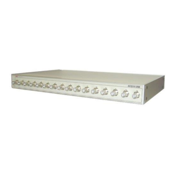
ACQ16 USB Acquisition Interface Unit The ACQ16 USB Acquisition Interface Unit is one of the available acquisition interfaces for the DSI/Ponemah software. An acquisition interface unit interfaces high-level analog signals into the P3 Plus system. The P3 Plus software is designed for the user whose application demands flexibility along with accurate, continuous, non-interrupted data monitoring, recording, and analysis in a standardized environment. -
Page 8: System Requirements
Your choice of instrumentation signal conditioning modules and analysis modules. Please view the P3 Plus Manual for system requirements. For information on DSI/Ponemah products and services, check out our website at www.datasci.com. 6 • System Overview ACQ16 USB Installation Manual... -
Page 9: Configuring The System
Parts List The following items comprise the system: Acquisition Interface Unit Model ACQ16 USB PNM-P3P-USB16 software on CD CD with license file P01989-1 USB software key P02124-2 - USB interface cable (2 meters) J02936 - BNC Cable set labeled 1-8 J02937 - BNC Cable set labeled 9-16 Configuring the System •... -
Page 10: Software Installation
Next button. A bubble should appear in the lower right hand corner of the screen stating that new hardware was found and that it was the DSI Ponemah ACQ16 USB. On the Found New Hardware Wizard dialog, select the Install the software automatically (Recommended) option, and click on the Next button. -
Page 11: Usb Port Connector
USB Port Connector The ACQ16 connects to the host computer via the USB 2.0 connector on the rear of the unit. The ACQ16 USB port is backward compatible with USB 1.1. However, only when connected to a USB 2.0 compatible computer, will the ACQ16 USB be able to download data to the computer at its maximum speed. - Page 12 The ranges allow you to set up the ACQ16 USB for full-scale compatibility with most common signal conditioning systems. 10 • Configuring the System ACQ16 USB Installation Manual...
-
Page 13: Getting Started
Getting Started Introduction Before turning on the Acquisition Interface power, be sure the line voltage is within the power supply specifications. The power switch for the Acquisition Interface is located on the rear of the unit. A green light located on the front panel illuminates when power is ON. The only operating control for the Acquisition Interface is the span settings in the P3 Plus software. - Page 14 User Name Dialog The User Name that is entered will be recalled automatically the next time the system is started. The name entered here will be used on all printouts and audit logs for identification of the data collected. After clicking on the Continue button, the Main Menu screen will be displayed. You are now ready to begin setting up, acquiring, and analyzing your input data.
-
Page 15: Calibration Dialog
Calibration Dialog Configuring the ACQ16 USB A group of tabs appears when 7700 Amplifier Setup is selected from the Calibration menu. This will include General, Configuration, and Descriptions tabs, which are accessed by their own tabs. General Tab The General Tab allows the user to set up channel specific signal conditioner parameters. - Page 16 This column is useful in troubleshooting the signal conditioner input connection. Label Label allows you to type in a logical name of up to 10 additional characters for a particular input channel. The chosen name will be saved and used to identify the input data throughout the system, such as in the dialog that displays input channel information.
- Page 17 Units This column displays the units that have been set in the Configuration tab and cannot be changed in this tab. The Units have no effect on the channel and it is for documenting the Input units. Calibration Dialog • 15 ACQ16 USB Installation Manual...
-
Page 18: Configuration Tab
Configuration Tab To set up the actual signal input configuration, select the Configuration tab in the signal conditioner setup panel. The Configuration set up screen as shown below will be displayed. ACQ16 USB Configuration Tab Value This column continuously displays the current value that is on the input of the signal conditioner. - Page 19 Units, High Unit and Low Unit, of measure should be set up. This calibrates the channel to the actual user units and scaling. The system will now display, record, and perform analysis directly in your units of measure. System defaults are: -5 Low Cal = -5 Low Unit and +5 High Cal = +5 High Unit.
-
Page 20: Descriptions Tab
Descriptions Tab The Descriptions tab allows the user to enter a text description for each input. The Descriptions Menu allows you to enter text to further describe the parameters being recorded. This may include additional user information or test setup information. -
Page 21: Voltage View And Resetting
Voltage View and Resetting The ACQ16 USB has the capability of viewing its values for debugging purposes and also resetting each channel if a problem has occurred during setup. Voltage View This view allows the user to see the raw voltage that is being inputted into the channels. -
Page 22: Reset
Voltage View To return back to normal view, select Voltage View again. Reset This selection allows the user to reset the settings of the channel selected. When selected, the channel will reset all values back to the default settings. See the individual sections for the default values. -
Page 23: Appendix
Appendix Specifications Electrical Line Voltage Auto-switching 100-240VAC (±10%) Line Frequency 50/60Hz Maximum Current 1A @ 120VAC Fuse Internal, not serviceable Analog Inputs Number Channels Maximum Input Voltage 30V Peak Spans ±1.25, ±2.50, ±5.00, and ±10.00 Input Impedance 100kΩ Acquisition System Maximum Aggregate Sample Rate 250k samples per second Resolution... -
Page 24: Accessories / Replacement Parts
Pollution Degree Pollution Degree2, equipment shall be stored or operated where no conductive pollution occurs Installation Category Category 2, designed and tested to withstand limited over voltages Accessories / Replacement Parts Hospital grade power cable with NEMA 5-15P plug cap (P02198) (supplied) For North America 230V, a NEMA 6-15P plug cap may be required. -
Page 25: Rack Mounting
Rack Mounting The diagram below displays how to assemble the rack mount kit. Appendix • 23 ACQ16 USB Installation Manual... - Page 26 24 • Appendix ACQ16 USB Installation Manual...
-
Page 27: Maintenance
Maintenance Introduction This section describes routine maintenance procedures for the ACQ16 USB. If the units needs repair, consult a Service Representative. Service and repair are available only from the factory. Cleaning General Clean the case when necessary as described below. If the ACQ16 USB is used in dirty or dusty environments, cleaning should be performed more frequently. -
Page 28: Declaration Electromagnetic Emissions/Immunity
Declaration Electromagnetic Emissions/Immunity Electromagnetic Emissions/Immunity Tables Guidance and manufacturer’s declaration – electromagnetic emissions The equipment is intended for use in the electromagnetic environment specified below. The customer or the user of the equipment should assure that it is used in such an environment. Emissions Test Compliance Electromagnetic environment - guidance... - Page 29 Guidance and manufacturer’s declaration - electromagnetic immunity The equipment is intended for use in the electromagnetic environment specified below. The customer or the user of the equipment should assure that it is used in such an environment. Immunity test IEC 60601 test Compliance Electromagnetic environment - guidance level...
- Page 30 Guidance and manufacturer’s declaration - electromagnetic immunity The equipment is intended for use in the electromagnetic environment specified below. The customer or the user of the equipment should assure that it is used in such an environment. Immunity test IEC 60601 test level Compliance Electromagnetic environment - guidance level...
- Page 31 être employés comme dispositif de soutien de la vie. L'utilisation des produits de DSI/Ponemah sont seulement pour les buts de conduire la recherche de la science de vie.
- Page 32 CONSIDÉRATIONS OPÉRATIONNELLES DE SÛRETÉ SOURCE D'ÉNERGIE Cet instrument est prévu pour fonctionner à l'intérieur à partir d'une source d'énergie qui n'applique pas plus de 250 volts de RMS entre les conducteurs d'approvisionnement ou entre l'un ou l'autre conducteur d'approvisionnement et la terre. Une prise de terre protectrice par le conducteur de terre dans le cable électrique est exigée.
Need help?
Do you have a question about the PNM-P3P-USB16 and is the answer not in the manual?
Questions and answers