Subscribe to Our Youtube Channel
Summary of Contents for Fluke EI-162BN
- Page 1 ® EI-162BN Split-Core Transformer Users Manual PN 2842250 June 2007 © 2007 Fluke Corporation, All rights reserved. Printed in the Netherlands. All product names are trademarks of their respective companies.
- Page 2 Fluke's warranty obligation is limited, at Fluke's option, to refund of the purchase price, free of charge repair, or replacement of a defective product which is returned to a Fluke authorized service center within the warranty period.
-
Page 3: Table Of Contents
Table of Contents Title Page Introduction ..................1 Unpacking..................... 1 Packing ....................1 Safety Regulations ................2 Symbols ....................3 Accessories ................... 4 Features....................5 Using the Split-Core Transformer............6 Installing Transformer around Pylon Footing ........6 Determining Transformation Ratio Connections ......8 Connecting Transformer to Earth Ground Tester...... - Page 4 EI-162BN Users Manual...
- Page 5 List of Tables Table Title Page Features and Functions ................. 5 Transformation Ratios ................8...
- Page 6 EI-162BN Users Manual...
- Page 7 List of Figures Figure Title Page Features....................5 Installing Transformer Around Pylon ........... 7 Transformation Ratio Connections ............9 Test Measurement Setup............... 11...
- Page 8 EI-162BN Users Manual...
-
Page 9: Introduction
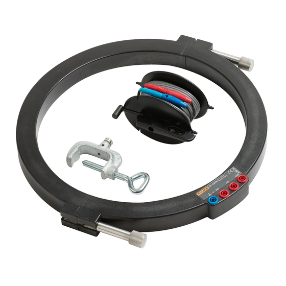
EI-162BN Split-Core Transformer Introduction The Fluke EI-162BN Split-Core Transformer (hereafter referred to as the “Transformer”) is used with an earth ground tester (hereafter referred to as the “Tester”) to make selective earth ground resistance measurements (R ) on transmission line pylons. The Transformer is designed to work with Fluke 1625 and 1623 GEO Earth Ground Testers. -
Page 10: Safety Regulations
EI-162BN Users Manual Safety Regulations This device is only to be installed and operated by qualified personnel in compliance with the safety precautions and regulations that follow. Additionally, use of this device requires compliance with all legal and safety regulations pertaining to each specific application. Similar regulations apply to the use of accessories. -
Page 11: Symbols
Split-Core Transformer Symbols • Assume that safe operation of the device is not possible if it shows visible damage. • Assume that safe operation of the device is not possible if it has been exposed to unfavorable conditions (for example, storage beyond the permissible climatic limits without adaption to the ambient climate and dewing). -
Page 12: Accessories
Transformer to the Tester’s jack. The female red and blue leads then plug onto the male red and blue banana plugs on the sensing cable adapter used with the Fluke 1623 and 1625 for selective resistance measurements. (Sensing cable adapter, Fluke part number 2539195). -
Page 13: Features
Split-Core Transformer Features Features See Figure 1 and Table 1 for Transformer features and functions. evx01.eps Figure 1. Features Table 1. Features and Functions Item Description Transformer half (2) Transformer end faces have bolts that pivot to aid in separating the Transformer halves One Transformer end face has a slotted bolt hole that allows the bolt to pivot out of the end face... -
Page 14: Using The Split-Core Transformer
EI-162BN Users Manual Using the Split-Core Transformer Installing Transformer around Pylon Footing To install the Transformer around a pylon footing: 1. Loosen (or if required, remove) the fasteners. See Figure 2. If extra leverage is needed to loosen a fastener, insert a lever (like a small screwdriver) into the 4 mm bore hole in the fastener. - Page 15 Split-Core Transformer Using the Split-Core Transformer evx02.eps Figure 2. Installing Transformer Around Pylon...
-
Page 16: Determining Transformation Ratio Connections
EI-162BN Users Manual Determining Transformation Ratio Connections Before you connect the Transformer to the Tester, you need to determine a suitable transformation ratio for the minimum measuring and maximum parasitic currents expected to flow through the transmission line pylon. The Transformer has 1000 windings, with connections at winding ratios of 1000, 500, 200 and 0 (⊥). - Page 17 Split-Core Transformer Using the Split-Core Transformer 1 : 200 1 : 300 1 : 500 1 : 800 1 : 1000 evx03.eps Figure 3. Transformation Ratio Connections...
-
Page 18: Connecting Transformer To Earth Ground Tester
Plug the test lead into the bore hole in the clamp and tighten the tightening screw. See Figure 4. For Fluke 1625 / 1623 GEO Earth/Ground Testers, the earth ground electrode jack is labeled C1 or E. 3. Install the 12-m (40-ft) test leads from the Tester’s Ajack to the Transformer’s transformation ratio connections. - Page 19 Split-Core Transformer Using the Split-Core Transformer Parasitic Current Aux. Probe Earth Electrode FLUKE 1623 Earth/Ground Tester FLUKE Measuring Current evx04.eps Figure 4. Test Measurement Setup...
-
Page 20: Maintenance
EI-162BN Users Manual Maintenance Only trained and qualified staff should perform maintenance on this instrument. In all repair and reconditioning work, ensure the Transformer’s design parameters are not modified to the detriment of safety, that only authorized parts are used, and that parts are reassembled to their factory-issued configuration. -
Page 21: Specifications
Split-Core Transformer Specifications Specifications Note Fluke reserves the right to modify specifications without notice for the purpose of product improvement. General Temperature Range Working Temperature ......... -10 °C to +50 °C (+14 °F to +122 °F) Storage Temperature ......... -30 °C to +60 °C (-22 °F to +140 °F) Dimensions Outer diameter............ -
Page 22: Service
If it still fails to operate properly, pack securely using the original packing material (if available) and forward, postage paid, to the nearest Fluke Service Center. Include a brief description of the problem. Fluke assumes no responsibility for damage in transit.

Need help?
Do you have a question about the EI-162BN and is the answer not in the manual?
Questions and answers