
Related Manuals for maximatecc CCpilot VI


Summary of Contents for maximatecc CCpilot VI
- Page 1 Technical manual Date: Jul 6, 17 CCpilot VI Technical manual www.maximatecc.com...
-
Page 2: Table Of Contents
CCpilot VI - Technical Manual Date: Jul 6, 17 Contents Contents .............................2 Introduction ..........................3 1.1 Product models .......................... 3 1.2 Conventions and definitions ....................4 1.3 Identification ..........................4 1.4 Care ............................. 4 1.5 Environment and Environmental Tolerance ................. 5 1.6 Cleaning ............................ -
Page 3: Introduction
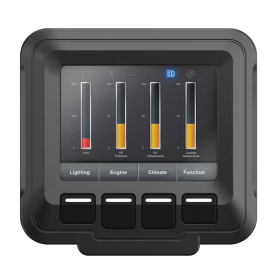
Introduction CCpilot VI is an easily configurable, full-colour 3’’5 display enabling appealing user interfaces in a compact form factor. Designed especially for the off-highway and industrial markets, CCpilot VI offers exceptional readability and all-weather performance. It is suitable for both bracket mounting and integration in a dashboard. -
Page 4: Conventions And Definitions
Consider traffic safety when CCpilot VI is installed and whenever it is used. maximatecc does not recommend that CCpilot VI or its accessories be used actively by the driver when a risk of injury to people, or damage to property, is present. -
Page 5: Environment And Environmental Tolerance
To ensure proper and reliable functionality over time, the unit shall be wiped cleaned of dirt and dust. Use a suitable light damp rag to clean the unit. Never use alkaline, alcoholic or other chemicals for cleaning which can damage the unit. www.maximatecc.com... -
Page 6: Overview
Connectors. There are also mounting holes for fasteners for attaching the RAM mount shown or bracket for panel mounting. GORE-TEX membrane, under mount for added protection External connectors RAM mount (purchased separately) www.maximatecc.com... -
Page 7: Installation
2 mA. The fuse F2 fuse rating and wire gauge shall be dimensioned for the total switch current. Connector (J1) 10 A Min: AWG 16 Min: AWG 16 BATTERY 2 mA XXm A Unit A Unit B www.maximatecc.com... -
Page 8: Mounting
An alternate mounting method would be in a panel using the 123233 Mounting kit. Ensure that CCPilot VI is mounted to a smooth, flat surface. Fastening the unit to an uneven surface may stress the enclosure, damage the outer flange or possibly even flex the circuit board inside, leading to a premature failure. -
Page 9: Cables
When CCpilot VI or any device is installed in a vehicle environment it is important that the installation is traffic-safe. maximatecc does not recommend that CCpilot VI or its accessories are used actively by the driver or operator when a risk of injury to people, or damage to property, is present. -
Page 10: Basic Operations
This section covers basic operation of the VI device such as start-up and shut-down. 1.13 Starting Up Start CCpilot VI via the vehicle’s ignition switch. A menu will appear on the CCpilot VI’s LCD screen as an indication that the unit is starting up. -
Page 11: Interface Overview
See the section standard product model equipment level for information on the respective unit configuration. 1.17 Storage memory 16 Mbytes of NAND Flash memory is used for data storage. A 64 Mbyte version of the CCpilot VI is also available. 1.18 Buzzer A buzzer that can be used for user notifications exists on the VI. -
Page 12: Connectors
Pin # Default signal Comments 12-pin Deutsch DTM Series Key B Configurable Input 1 Configurable Input 2 Configurable Input 3 Configurable Input 4 Analog Ground CAN 2 Shield CAN 2+ CAN 2- Not Used Not Used Not Used Not Used www.maximatecc.com... -
Page 13: Specifications
Specifications The specification may vary depending on your computer configuration. Standard models connectivity level Interface / Feature CCpilot VI CAN bus USB Host Configurable Inputs Switched Outputs 1.23 Technical data Kernel Processor Freescale Kinetis K70, ARM Cortex M4, 150 MHz... -
Page 14: Environmental Tolerance
44-55 54-65 400-1000 EMC Radiated RF immunity EN 61000-4-3 RF electromagnetic field 80M-1GHz 10V/m 1G-2GHz 3V/m 2G-2,7GHz 1V/m EMC Induced RF 1) EN 61000-4-6 0.15-80MHz 10V EMC Radiated RF emission CISPR 25 dBµV/m .150-54MHz 230-1000MHz Enclosure EN 60529 IP65 www.maximatecc.com... - Page 15 FCC Notice to Users Users are not permitted to make changes or modify the device in any way. Changes or modifications not expressly approved by the party responsible for compliance could void the user’s authority to operate the equipment. www.maximatecc.com...
-
Page 16: Weight And Dimensions
1.25 Weight and dimensions CCpilot VI 3.5” Description Enclosure size 107.7 x 103.1 x 42.7 mm (W x H x Weight 198 g www.maximatecc.com... -
Page 17: Technical Support
Operating system type and its version number. The VI Device log files (if possible) Prepare a system report on the VI device, from within CCsettings (if possible). Information regarding possible external equipment which is connected to the VI device. www.maximatecc.com... -
Page 18: Trade Mark, Etc
For end-user license agreements (EULAs), copyright notices, conditions, and disclaimers, regarding certain third-party components used in the VI device, refer to the copyright notices documentation. www.maximatecc.com... -
Page 19: Index
GPS ................ 11 Trade Mark ............18 Turning off ............10 Turning on ............10 Hook up of Power supply ........7 USB .................11 Inputs ..............12 Installation .............. 7 Installing cables ............ 9 Vehicle´s fuse ............7 Introduction ............3 Weight ..............16 www.maximatecc.com...
Need help?
Do you have a question about the CCpilot VI and is the answer not in the manual?
Questions and answers