Sign In
Upload
Download
Add to my manuals
Delete from my manuals
Share
URL of this page:
HTML Link:
Bookmark this page
Add
Manual will be automatically added to "My Manuals"
Print this page
×
Bookmark added
×
Added to my manuals
Manuals
Brands
Aiwa Manuals
Recording Equipment
CSD-A190 LHS
Service manual
Aiwa CSD-A190 LHS Service Manual
Cd stereo radio cassette recorder
Hide thumbs
1
2
3
4
5
6
7
8
9
10
11
12
13
14
15
16
17
18
19
20
21
22
23
24
25
26
27
28
29
30
31
32
33
34
35
36
37
38
page
of
38
Go
/
38
Bookmarks
Advertisement
Quick Links
Download this manual
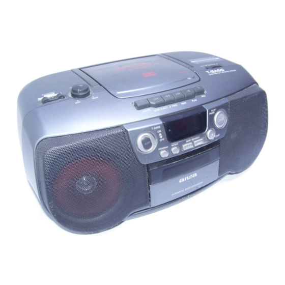
CSD-A190
LH(S,L)
SERVICE MANUAL
CD STEREO RADIO
BASIC TAPE MECHANISM:TN-21ZVC-2000
CASSETTE RECORDER
BASIC CD MECHANISM :KSM-213 RDM
S/M Code No. 09-029-456-0N3
Table of
Contents
Previous
Page
Next
Page
1
2
3
4
5
Advertisement
Need help?
Do you have a question about the CSD-A190 LHS and is the answer not in the manual?
Ask a question
Questions and answers
Related Manuals for Aiwa CSD-A190 LHS
Recording Equipment Aiwa CSD-A110 U Service Manual
Compact disc radio cassette recorder (18 pages)
Recording Equipment Aiwa CSD-A510 Service Manual
Cd radio cassette recorder (30 pages)
Recording Equipment Aiwa CSD-A280LH Service Manual
Compact disc stereo cassette recorder (27 pages)
Recording Equipment Aiwa CS-P500W Service Manual
Stereo radio cassette recorder (7 pages)
Recording Equipment Aiwa CSD-A190 LHL Service Manual
Cd stereo radio cassette recorder (38 pages)
Recording Equipment Aiwa HV-FX6500 Service Manual
Stereo video cassette recorder (27 pages)
Recording Equipment Aiwa HD-S1 Operating Instructions Manual
Digital audio tape recorder (22 pages)
Recording Equipment Aiwa XC-RW500 Operating Instructions Manual
Aiwa xc-rw500: user guide (18 pages)
Recording Equipment Aiwa XC-RW700 Operating Instructions Manual
Aiwa cd recorder operating instructions xc-rw700 (30 pages)
Recording Equipment Aiwa TP-S90 Service Manual
Cassette recorder (17 pages)
Recording Equipment Aiwa RM-77 Service Manual
Radio cassette recorder (8 pages)
Recording Equipment Aiwa RM-P33 Service Manual
Radio cassette recorder (6 pages)
Recording Equipment Aiwa HS-JS479 Service Manual
Stereo radio cassette recorder (9 pages)
Recording Equipment Aiwa HD-S1 Service Manual
Digital audio tape recorder (44 pages)
Recording Equipment Aiwa MM-FX500 Operating Instructions Manual
Portable mp3 recorder (36 pages)
Recording Equipment Aiwa GE-950 Operating Instructions Manual
Stereo graphic equalizer (28 pages)
This manual is also suitable for:
Csd-a190 lhl
Print
Rename the bookmark
Delete bookmark?
Delete from my manuals?
Login
Sign In
OR
Sign in with Facebook
Sign in with Google
Upload manual
Upload from disk
Upload from URL


Need help?
Do you have a question about the CSD-A190 LHS and is the answer not in the manual?
Questions and answers