
Summary of Contents for Ohkura EC5500R
- Page 1 EC5500R Digital Indicating Controller Instruction Manual DRAFT WXPEC5500R01E JLY 2005 (1st edition) All Rights Reserved, Copyright © 2005, Ohkura Electric Co., Ltd.
- Page 2 For Safety Using Thank you for purchasing our EC5500R Digital Indicating Controller. For proper and effective use of full functions of this instrument, please read and understand this instruction manual well before use. The following symbol marks are used in this instrument and the instruction manual for safety using.
- Page 3 Caution Input/output Do not use open terminals for other purposes such as relay. Inside of Do not disassemble the inside of the main unit. instrument [Caution] (1) Please deliver this instruction manual to the final user. Instruction (2) Be sure to read this instruction manual before handling the manual instrument.
- Page 4 Chapter 10 Troubleshooting ◎ ◎:Be sure to read the chapter ○:Read if necessary. Type of Instruction Manual Name Description This Describes the general manual EC5500R Digital Indicating information on EC5500R Controller Instruction Manual 1 including installation, wiring, WXPEC5500R01E operation and functions. RS-232C/RS-422A/RS-485...
-
Page 5: Table Of Contents
Table of Contents Chapter 1 Chapter 8 Operation ....38 When Product Arrives....5 8.1 Control Method......38 1.1 Checking the Accessories ..5 8.2 Automatic Control (AUTO) 1.2 Checking the Type..... 5 and Manual Control (MAN) ..38 1.3 Display........6 8.2.1 SP/Output Display Switching..38 8.2.2 AUTO/MAN Switching ....39 Chapter 2 Installation.... -
Page 6: Chapter 1 When Product Arrives
Chapter 1 When Product Arrives 1.1 Checking the Accessories When this product arrives, please check on the accessories and appearance and check that there is no lacking parts or damages. If you find any inappropriate parts, inform our dealer where you purchased the instrument or our sales representative. -
Page 7: Display
1.3 Display [Reference] Display character correspondence table The display characters used in this instrument and the alphabets indicated by them are shown in table below: Display character Alphabet A... -
Page 8: Chapter 2 Installation
Chapter 2 Installation Install this product by establishing holes according to the panel cut drawing and fixing it with the accessory fixtures. (Unit: mm) Panel cut Fixture Installation procedure Setscrew (96×(N-1)+92) +0.8 Installation of N pieces Mounting panel Attachment posture Instrument Attach within 30 front... - Page 9 Optional (communication External dimension diagram module) separately sold (*1) 100 11.3 Approx. 175 96 (7.4) Optional (communication cable) separately sold (*2) Panel thickness 10Max. Optional (DI cable) separately sold (*3) RS-232C RS-422A RS-485 Separately *1 Communication ZE7101A0 ZE7101B0408 sold module products *2 Communication HMSU2255...
-
Page 10: Chapter 3 Wiring
Chapter 3 Wiring Warning ・ N ever touch the power supply terminal while the power is supplied. When the power supply terminal is touched, it gets an electric shock. ・ N ever touch relay output terminal and alarm output terminal when they are connected with power supply. - Page 11 Dual output Single output Output 1st output 2nd output ① + ① + ③ + ○ ○ ○ Current Load Load Load ○ ○ ○ ② − ② − ④ − ① ① ③ drive Load Load Load ② ② ④ ③ ...
- Page 12 A CW ⑰ ⑫ B I/O ⑱ ⑬ CCW ● ⑲ Terminator ⑭ ● ⑳ CW ● Expansion I/F, servo drive ☞ Expansion Interface, Servo Drive Output Instruction Manual WXPEC5500R04E − −...
-
Page 13: Chapter 4 Part Names
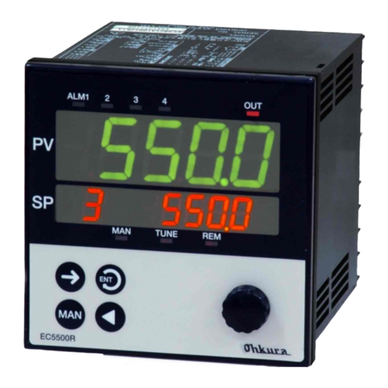
Chapter 4 Part Names ① Alarm/event display ② Output display □ SP No. display 3 □ Upper display 1 ③ MAN operation display □ Lower display 2 ⑤ Remote control Screen selection/group 1 display selection key ④ Tuning operation AUTO/MAN display 2... -
Page 14: Chapter 5 Basic Operation And Setting
Chapter 5 Basic Operation and Setting 5.1 Screen Type Power startup Normal display ☞ Operation screen Auto ☞ Press the key for approx. 3 seconds. restoration Select with key or dial and press the key. Parameter screen Auto restoration... -
Page 15: Selection Of Group/Item On Screen
5.2 Selection of Group/Item on Screen [Reference]What is a group? There are several “groups” classifying the items by kind on each screen. Each group is given with a name that indicates the kind. Group name is displayed on the upper display (except for SP or output display) on Operation screen and on lower display in group display on Parameter screen and Setup screen. -
Page 16: Data Setting Procedure
5.3 Data Setting Procedure Data is classified as “numeric data” and “character data.” Numeric value blinks when change is enabled for numeric data, and the decimal point blinks for character data. It is set up by the following procedure: [Caution] If there is no key or dial operation for more than 10 seconds while change is enabled, the value being changed is invalidated (original value is recovered) and change is disabled. -
Page 17: System Setup
5.4 System Setup The basic functions of this controller are as shown in the following table at factory setting. To use with settings other than that of factory setting, press the key for about 6 seconds to display the Setup screen and ... -
Page 18: All Reset
Input list Input Code Input range Input Code Input range TC (thermocouple) input DC voltage, DC current input 0 to 1820℃ -10.0 to 10.0mV B 0 to 1760℃ 0.0 to 20.0mV R 0 to 1200℃ 0.0 to 50.0mV R ... -
Page 19: Setting Items Of Each Function
5.6 Setting Items of Each Function This section describes the setting items and the order of setting for each of the major functions. 5.6.1 Set the Controlled SP Each Time Order Item Screen/group Factory setting Set the normal SP. ① Set the normal PID and MR (Manual P: 2.0% Reset: at PD control). -
Page 20: Use Of Alarms
5.6.3 Use of Alarms Order Item Screen/ Factory setting group DO1: Deviation high alarm Alarm function is DO2: Deviation low alarm ① determined. DO3: Deviation absolute value alarm DO4: Fail (it is not an alarm.) DO1: + scaling width Set the alarm DO2: - scaling width ②... -
Page 21: Gapped Control (Nonlinear Control)
5.6.4 Gapped Control (Nonlinear Control) Order Item Screen/ Factory setting group Switch the gapped control setting to Disabled ① “Enabled”. Gap gain = 0.01, ② Set the gap width and gap gain. PA13 gap width = 0 5.6.5 Remote SP Order Item Screen/... -
Page 22: Key Lock
5.7 Key Lock The key lock is the function to prevent setting by mistake. Set the key lock type in SU5 on Setup screen, and “Lock”/”Unlock” is specified in on Operation screen. The key lock type and key lock subjects are shown as follows. -
Page 23: Chapter 6 Operation Guidance
Chapter 6 Operation Guidance This chapter shows the transition chart of the display and the key operation. [Reference] How to look at guidance : key movement key movement : Bold frame: Displayed for factory setting Broken line frame: Displayed for optional equipment Italic: Cannot be set up. -
Page 24: Operation Screen
6.1 Operation Screen PV n. Key lock Normal SP Heater current n. PV Heater Multi SP resistance n PV Alarm hold Bias PV Indicate the upper display. PV Emergency Indicate the lower display ... - Page 25 Use of SP R/L Tuning Input type Multi SP Execution Communication Execution P Unit n SP No. Up rate Execution I Control ...
-
Page 26: Parameter Screen
6.2 Parameter Screen n.Function n. detail Heater Alarm value Multi P1 Multi P8 resistance setting high alarm value n.... - Page 27 To normal Output PV start Gap gain upper limit display Output Gap width lower limit 2nd output upper limit [Reference] Settings and functions For setting details and functions, refer to ...
-
Page 28: Setup Screen
6.3 Setup screen DO function DI function Multi output Input type selection selection SP No./PID Scaling H Control mode No. - Page 29 Baud rate R-SP range Key lock type AO range Use of Communication AO source Emergency address ...
- Page 30 n. Heater high alarm Dead band Local address Local address function selection . n. n. Heater high-high Servo status Master/slave Heater address alarm function selection ...
- Page 31 (Not used) To normal Pass number display [Caution] Pass number is the item for plant adjustment. Do not operate it. [Reference] Settings and functions For setting details and functions, refer to Chapter 7 (Details/setting range) and Chapters 8 and 9 (Functions). Furthermore, refer to Expansion Interface, Servo Drive Output Instruction Manual “WSPEC5500R04E”...
-
Page 32: Chapter 7 List Of Items
Chapter 7 List of Items 7.1 Operation Screen Upper display Factory Item () indicates SP Description/setting range setting Normal SP PV Scaling range Scaling range Multi SP PV(n) n: Multi SP No. (n=1 to 8) Bias 20% of ± scaling width (... -
Page 33: Parameter Screen
Upper display Factory Item () indicates SP Description/setting range setting Anti- Use of anti-overshoot ( ) overshoot : Not used, : Used Control : Control RUN ( ) : Control STOP SP R/L : SP local, : SP remote ... -
Page 34: Setup Screen
Upper Factory Item Description/setting range display setting Heater high Heater high alarm specified alarm specified n. temperature Scaling range temperature Heater alarm Heater alarm judgment lower judgment lower n. temperature scaling range temperature Heater alarm Heater alarm judgment upper judgment upper 1500 n.... - Page 35 Upper Factory Item Description/setting range display setting Sensor -100.0℃ to 100.0℃ correction Reference Reference junction compensation junction : Disabled, : Enabled compensation Square root : Disabled, : Enabled Input cutoff Input cutoff level at square root. 10.0 ...
- Page 36 Upper Factory Item Description/setting range display setting SU3 DO functions n: DO No. (n = 1 to 4) Alarm: : Deviation high alarm, n. Deviation low alarm, n. : Deviation absolute value high alarm, n. : PV high alarm, n. : PV low alarm, n. : SP high alarm, n.
- Page 37 Upper Factory Item Description/setting range display setting ☞ SU7 Isolated remote SP Function details AO, Isolated Remote SP Instruction Manual WXPEC5500R03E Remote SP range R-SP range :1 to 5V, :0 to 5V emergency : Not used, : Used ...
- Page 38 Upper Factory Item Description/setting range display setting SU11 Heater monitoring n: Heater No. (n = 1 to 3) ☞ Function details, Expansion Interface, Servo Drive Output Instruction Manual WXPEC5500R04E Local address Expansion I/F local address 0 to 255 Heater address Expansion I/F heater address 0 to 63 ...
-
Page 39: Chapter 8 Operation
Chapter 8 Operation 8.1 Control Method Control methods are classified into automatic operation (AUTO) and manual operation (MAN). Control Output method lamp Output is calculated by controlled computing of AUTO PID, etc. Output cannot be set manually. Operation is executed with the set output. 8.2 Automatic Control (AUTO) and Manual Control (MAN) 8.2.1 SP/Output Display Switching ... -
Page 40: Auto/Man Switching
8.2.2 AUTO/MAN Switching When key is pressed with MAN lamp blinking (refer to Sec. 8.2.1 on previous page), the control switches to MAN if the current control is AUTO and to AUTO if the current control is MAN. AUTO→MAN switching MAN→AUTO switching Operation screen... -
Page 41: Normal Sp And Multi Sp
8.3 SP 8.3.1 Normal SP and Multi SP In this instrument, values can be registered for normal SP and 8 kinds of SPs (multi SP) assigned to No.1 to 8. There is a couple PID for each SP and it automatically switches to the PID to be used in interlock with the SP to be executed (except when remote SP is ☞... -
Page 42: Pv Start
8.3.3 PV Start PV start functions at multi SP switching or at turning on the power during ramping or multi SP execution. However, it is limited to cases in which the down rate setting is not 0 (OFF) if PV > target SP and the up rate setting is not 0 (OFF) if PV <... -
Page 43: Self Tuning
8.5 Self Tuning Unlike automatic tuning which is executed only when the operator intends, Self tuning is the function to execute automatic tuning when the stability of control exceeds the limit or setting changes in steps, etc. by monitoring the existence of deviation, hunting, etc. continuously from the controller. Since the output is not changed in steps as in automatic tuning, there is no disturbance by tuning. -
Page 44: Selection Of Operation Method
8.6 Selection of Operation Method Operation method is selected by the setting on SP remote/local, SP No./PID No. selection and PID mode. The SP No. switching method and the SP and PID to be used are decided by these settings. The relationship between these settings and action is shown in the table below: ×: Setting does not affect. -
Page 45: Power Failure And Power Restoration During Operation
8.7 Power Failure and Power Restoration during Operation If power failure occurs during operation, the action at power restoration will be as follows: Power failure Approximately period Approximately 50msec or longer 50ms or shorter Item Display Normal display will be shown. SP in execution SP action... -
Page 46: Chapter 9 Procedure For Major Functions
Chapter 9 Procedure for Major Functions 9.1 Alarms 9.1.1 Pause Alarm This function is validated after turning on the power or after changing the setpoint (SP) or alarm value. An alarm doesn't occur even if it is in an alarm range (both or either of PV and SP at values where an alarm is occurred if usual) if it doesn't pass in a normal range (both PV and SP at values where an alarm is not occurred). -
Page 47: On Delay Type
9.1.3 ON Delay Time This is the function to delay alarm generation for the setting period when it turned on the power (in alarm range) or when it shifts from normal range to alarm range. High alarm value Low alarm value Time→... -
Page 48: Square Root
9.3.2 Square Root Enabled for mV (except 0.0 to PV ±10.0mV), V, mA input. The (%) following formula is used to ↑ calculate the process variable (PV) from input: PV= √input x 10 Furthermore, PV= 0 is set compulsorily if input is smaller than the input cutoff level. -
Page 49: Profiling Control
9.6 Profiling Control It is a type of cascade control in which the range of remote setting value change for the slave controller is restricted. Master controller adds the value obtained by converting -50 to +50% with 50% PID computing result as 0% into ±7% with the master setting value converted into %, and transmits it to the slave controller. -
Page 50: Gapped Control (Nonlinear Control)
9.7 Gapped Control (Nonlinear Control) Nonlinear PID control is the control method in which deviation changes the proportional gain inside/outside the gap width centering on setting value (SP). ・ When|Deviation|≦ gap, : Proportional gain x gap gain ……output change is small. ・... - Page 51 The action in each control mode is as follows (dead band > 0): 1)PID or PD control for both outputs Cooling Heating output output →PID operation result Dead band 2)ON-OFF for 1st output, PID control for 2nd output Hysteresis width for heating Cooling Heating output...
-
Page 52: Chapter 10 Troubleshooting
Chapter 10 Troubleshooting Trouble Cause Remedy Check the power supply voltage and power supply wiring. If power Nothing is Power supply is supply voltage and wiring are displayed. not input correctly. correct, contact our dealer where you purchased the instrument or our sales representative. - Page 53 Trouble Cause Remedy Contact our dealer where There is an error in you purchased the calibration data. instrument or our sales displayed. *1 representative. Contact our dealer where There is an error in optional you purchased the card. instrument or our sales displayed.
- Page 54 − −...
- Page 55 − −...
- Page 56 (or on case surface). Ohkura Electric Co., Ltd. Website http://www.ohkura.co.jp / Headquarters/plant 1-4-4 Nissai Hanamizuki, Sakado-shi, Saitama 〒350-0269 TEL: 049-282-7755(key) FAX:049-282-7001(key) Osaka Branch Daihoku building, 3-9-13 Nishinakajima Yodogawa-ku, Osaka-city 〒532-0011...
Need help?
Do you have a question about the EC5500R and is the answer not in the manual?
Questions and answers