Advertisement
Quick Links
Advertisement

Summary of Contents for EA4TX InterlockV3
- Page 1 EA4TX InterlockV3 EA4TX Interlock Users manual March/2020 Rev 3.1h...
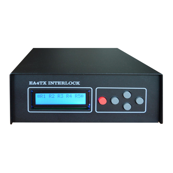
- Page 2 Introduction The Interlock is a device intended for use by multioperator contest groups, which allows monitoring and control of up to 5 radios, and avoiding rule violation in M/S or M/2 in so far as number of signals on the air refers. The interlock connects to each radio through two ways: •...
- Page 3 Please read the manual carefully before connecting the device. If you have any doubts of problems, please contact: Postal address: Interlanco Comunicaciones At:. Pablo García - EA4TX Albasanz 48-50 4º Derecha 28037 Madrid - SPAIN E-mail: ea4tx@ea4tx.com Web: http://www.ea4tx.com...
- Page 4 Section1 EA4TX Interlock V3 Hardware The interlock has the following connections: • Power cable for 12-14Vdc. • Interface with 5 radios using DB9 connectors. • USB connector for firmware updates The device has the following connections, seen from the inside: •...
- Page 5 1.1 Sockets R1 – R5: DB9 connection for Radio interface The interlock supports up to 5 radios, two of which (R4 and R5) can be configured as Inband. Each one of these radios has to be connected via the corresponding DB9 socket. Here is the rear view of the device: Rear view of the interlock 1.2 DB9 pinout...
- Page 6 In the radios that don’t have an Inhibit input, the method to stop transmission is: • SSB: Routing the microphone signal through the relay at pins 3 and 8 of the DB9. When idle, the pins are connected, but when the block is activated the relay isolates the pins and the radio cannot send any SSB signals (no input Mic) •...
- Page 7 Section2 Configuration To enter the Interlock program menu, press the red button or F1. The interlock will immediately enter the programming mode, showing option screens as follows ⇧ • To go to the next menu, press (up arrow). ⇩ • To return to the previous menu, press (down arrow).
- Page 8 • Disabled: There is no radio 4, so its status is not checked • Normal: Radio 4 is a normal radio (not an Inband) • Inband->R1: Radio 4 is an Inband radio paired with Radio 1 • Inband->R2: Radio 4 is an Inband radio paired with Radio 2 •...
-
Page 9: Operation
Section 3 Operation The interlock detects and decides in tenths of a microsecond if a radio has activated the PTT and decides whether it needs to take action on this or any other active radio. In order to do this it uses an algorithm which prioritizes jobs with respect to others. So for example it will prioritize when comparing a radio and its Inband partner, since under no circumstance can both of these radios put a signal on the air at the same time. - Page 10 3.1: Example Multi-Single 1 RUN and 4 Multis: This is an example of a Multi/Single station with 1 RUN station and 4 (or less) multiplier stations 3.2: Example Multi-Single 1 RUN and 1 INBAND and 3Multis: In this other Multi/Single scenario, there is 1 RUN (R1) and its Inband (R4) plus 3 (or less) multiplier stations.
- Page 11 3.3: Example Multi/2 with 2 RUN and 3 Multis: Este es un ejemplo de una configuración de una estación Multi/2 con dos radios RUN (R1 y R2) y 3 (o menos) estaciones en modo Multiplicadoras.This is an example of a Multi/2 configuration with 2 RUN radios (R1 and R2) and 3 (or less) multiplier stations 3.2: Example Multi/2 with 2 RUN and their INBAND plus 1 Multis: In this final example we have a Multi/2 with 2 RUN (R1 and R2) and their respective...
- Page 12 Annex I – Connection for Yaesu radios Yaesu radios (FT1000, FT1000MP, 20000, etc) use a DIN connector like this one: The connection that needs to be made between the interlock interface (DB9) and the DIN connector is as follows: Remember that you need to insert a 10K Ohm resistor between pins 1 and 8 of the connector, as shown in this photo: Page 12 Manual Interlock-IP –...
- Page 13 Annex II – Connection for Yaesu FTDX101D/MP This Yaesu model uses a DB15 female connector. The pins that are going to be used on this DB15 connector are as follows: Pin1 +13.5V (pullup) Pin2 TX Ground Pin3 Pin8 TX Inhibit Page 13 Manual Interlock-IP –...
- Page 14 Annex III – Connection for the Elecraft K3 In the K3 we use the ACC connector. The pins used are as follows: Pin1 FSK IN (pullup a +5V) Pin5 Pin7 TX Inhibit Pin10 Key Out The connection that needs to be made between the interlock’s DB9 and the ACC is as follows: Remember that you need to insert a resistor (10K ohm for example) between pins 1 and 7 of the ACC connector.
- Page 15 Annex IV – Connection for the Flex 6400/6600 Those Flex models includes a DB15 Accessory Connector that will be used. The pins used are as follows: Pin 5 Gnd Pin 13 TX Inhibit Pin 11 Key Out The connection that needs to be made between the interlock’s DB9 and the Accessory Connector is as follows: Those Flex doesn’t need the pull-up resistor since it already includes it.
- Page 16 Annex V – Connection via Auxiliary Box As an additional option, it’s available the Auxiliary Box that will help you as interface with transceivers that don’t support an Inhibit signal. In those cases, you must pass the Mic, PTT and CW signals via this box. In other words, the Aux Box will be in serie with those signals.
- Page 17 Connect the out signal (@ Aux Box) to a new cable that ends with a Jack. This Jack will be connected to the transceiver (CW) Auxiliary Box mounted in an enclosure In this case, the Auxiliary has been set in series with the Mic, PTT and CW signals coming from microHAM device.
- Page 18 Annex VI – Connections for other radios In radios that do not have an Inhibit input, what we do is route the Mic signal (in SSB) or the CW signal (CW Mode) through pins 3 and 8 on the DB9 connector. As already indicated in the Hardware section (Page 6) the interlock has one relay per radio present between pins 3 and 8 on each connector.
- Page 19 Annex VII – Response times The response time measured from when a PTT signals activated in a radio, it’s analysis and if required, blocking a Radio, takes between 200 to 400 microseconds and depends on the position of the radio. The analysis starts at Radio1 and ends at Radio 5.
- Page 20 [This page has been left blank on purpose] Page 20 Manual Interlock-IP – User guide...
- Page 21 Index Introduction ....................2 About this manual ..................3 EA4TX Interlock V3 Hardware ............... 4 1.1 Sockets R1 – R5: DB9 connection for Radio interface ......5 1.2 DB9 pinout ....................5 1.3 Jumpers JP-1, JP-2, JP-3, JP-4 and JP-5, ..........6 1.4 J1: External power ..................
Need help?
Do you have a question about the InterlockV3 and is the answer not in the manual?
Questions and answers