Advertisement
Quick Links
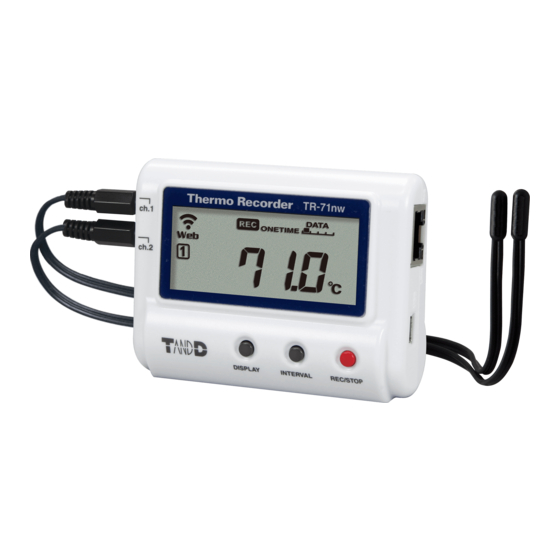
TR7 Series Thermo Recorder TR-71nw / 72nw / 75nw / TR-75wb
Please Read First
Package Contents
TR-71nw
Temperature 2ch
Data Logger
Temperature Sensor
AA Alkaline Battery
TR-0106 x 2
(LR6) x 2
TR-72nw
Temperature 1ch, Humidity 1ch
Data Logger
Temperature-
AA Alkaline Battery
Humidity Sensor
(LR6) x 2
THA-3001
TR-72nw-S
Temperature 1ch, Humidity 1ch
Data Logger
High Precision
AA Alkaline Battery
Temperature-Humidity
(LR6) x 2
Sensor SHA-3151
TR-75nw / TR-75wb
Thermocouple (K, J, T, E, S, R) Temperature 2ch
Data Logger
AA Alkaline Battery
USB Mini-B Cable
(LR6) x 2
(US-15C)
* Please prepare a thermocouple separately. T&D does not handle the sale of thermocouple sensors.
Part Names
TR-71nw / TR-72nw /
TR-72nw-S
Sensor Jack
Channel 1
Sensor Jack
Channel 2
(TR-71nw only)
Power Button
Thermocouple
Input Terminal
Safety Precautions and Instructions
The following items should be strictly obeyed for the safe usage
of this product, and for protecting yourself and other people
from bodily harm and/or damage to property.
Explanation of Symbols
<Warning Symbols>
These entries are actions that absolutely under no
circumstance should be taken. The taking of such an
DANGER
action may cause serious personal physical damage or
death.
These entries are actions that if taken may lead to
CAUTION
physical injury or damage to persons or things.
<Picture Symbols>
Denotes an
Denotes a
important warning
forbidden action.
or caution.
DANGER
To Prevent Serious Accidents
Do not disassemble, repair or modify the unit and/or accessories.
Do not use the unit in any environment that is exposed to chemi-
cals and harmful gases. Doing so may cause corrosion and/or
other danger to the unit. Also, coming in contact with hazardous
substances may cause bodily harm to the user or people nearby.
This product is not water resistant. If water or a foreign object
enters the case, immediately remove batteries and stop using it.
Do not touch the unit or AC adaptor during thunder and lightning,
as this may cause electrocution.
Do not handle the unit, remove batteries or cables with wet hands.
This product has been designed for private and/or industrial use
only. It should not be used in situations where strict safety precau-
tions are necessary such as with medical equipment, or in systems
directly or indirectly connected with human life or well-being.
Do not drop or expose the unit to a strong impact.
Do not cut or process the cords for the communication cables.
Also, do not twist, pull on or swing any of the cords.
To prevent damage to the unit from static electricity, remove static
electricity from your body by touching metal around you (such as
a door knob and window frame) before touching the unit.
USB Mini-B Cable
Manual Set
(US-15C)
(Warranty Included)
USB Mini-B Cable
Manual Set
(US-15C)
(Warranty Included)
(High-Precision Type)
USB Mini-B Cable
Manual Set
(US-15C)
(Warranty Included)
Manual Set
Registration Code
(Warranty Included)
Label
TR-75nw / TR-75wb
Operation Buttons
The Introductory Manual also explains operations using the operation buttons.
Place and store the unit and accessories out of the reach of chil-
dren.
We are not responsible for any damage, malfunction or trouble,
whether direct or indirect, caused by the use of our product.
Do not use any battery, sensor, or cable other than those specified
by T&D Corporation.
Do not put anything on top of the cable or the unit. This may
cause overheating.
Do not disconnect the USB cable during USB communication. Do-
ing so may cause adverse effects to the unit and/or PC.
Make sure that sensor and cable plugs are all inserted fully, so as
not to cause an improper connection. Also, when unplugging the
cable from the unit, do not pull the cord, but hold the connector to
disconnect.
If the unit produces heat, emits smoke or a strange smell, or
Denotes an action
makes unusual noise, immediately remove the batteries and stop
that should not be
using it. Also, unplug the unit from the PC.
carried out.
If the unit is not to be used for a long period of time, remove bat-
teries. Leaving batteries inside the unit may cause battery leakage
and malfunction. Install new batteries when starting or re-starting
to use a unit.
For TR-75nw / TR-75wb: Ch.1 and Ch.2 terminals are NOT electri-
cally isolated from each other. Do not attach non-isolated thermo-
couple sensors to objects connected to a live voltage. This may
cause a short circuit or an electrical shock.
CAUTION
» Areas exposed to direct sunlight
» Areas subject to direct flames or heaters, as well as areas in which hot
air accumulates and creates extremely high temperatures
» Areas exposed to static electricity
» Areas exposed to strong magnetic fields
» Areas exposed to water leakage
» Areas subject to condensation or wet areas
» Areas exposed to excessive vibration
» Areas exposed to excessive smoke, dust or dirt.
CAUTION
» Use the unit in the specified operating environment. Do not use it for
any purpose other than for which it was designed.
» Condensation may occur inside the case when a unit is moved from
one environment to another where there is a great difference in tem-
perature.
» Do not use the unit in wet areas or places exposed to water such as
bathroom.
» When connecting the unit to your PC, make sure to follow all warnings
and directions from your computer manufacturer.
Getting Logger Ready for Installation
Battery Installation & Sensor Connection
Battery
Make sure to use new
batteries (including for
replacement) and insert
in the correct direction.
Registration
Code Label
About TR-71nw Internal Sensor
Channel 1 has an internal temperature sensor. When an external sensor is not connected, the
internal sensor will be used.
Registration
About TR-75nw / TR-75wb Input Terminal
Code Label
When connecting thermocouple wires to the input terminal, make sure that the positive and
negative connections are in the proper order. If the polarity is incorrect, changes in tempera-
ture will be reversed (when the real temperature increases, the measured temperature will
decrease).
Wiring Connections
Connect and disconnect the thermocouple wire from the hole while
pressing the input terminal button with a screwdriver or other such tool.
Do not try to pull out the wire without pressing the button.
Registration
Code Label
Compatible Wires
Single wire:
0.32 to
Twisted wire: 0.08 to 0.32
Diameter: 0.12
or more
Strip length: 9 to 10
Using GND
If measurements are unstable while using external power (USB or PoE), connect to the GND terminal.
» See the Introductory Manual for how to set and check thermocouple sensor type for TR-75nw / TR-75wb.
Battery Cover
Do not place or store in the following areas:
Other Precautions
TR-71nw
0.65
(AWG 28-22)
(AWG 28-22)
TR-75wb
TR-71nw / 72nw / 75nw
(Wireless LAN)
USB Port
Ethernet Port (LAN)
» We shall not guarantee the unit's operation if it has been connected to
a PC using a USB hub or a USB extension cable.
» Do not insert any foreign objects into any of the units' jacks.
» If the unit gets dirty, wipe it with a clean cloth.
» Make sure to remove dust and dirt from plugs of any cables.
» Battery terminals may provide insufficient contact due to age or vibra-
tion. This may lead to data loss.
» Please note that this document has been written based on the presup-
position that details about contracts with an Internet provider, specific
network environments and the set-up of any other necessary equip-
ment to enable network connection has already been taken care of by
the User and that connection has been confirmed as workable. T&D
Corporation shall not be responsible for any damages which a contrac-
tor, a user or a third party may suffer, whether direct or indirect, due
to the inability to communicate or use communication devices.
» Please be careful not to let a third party know of your registration
code. The registration code cannot be reissued or changed.
CAUTION
Notices about Sensors
» Do not connect any sensor to the unit other than those specified by
T&D Corporation.
» Make sure to use sensors within the measurement range indicated in
the specifications for that sensor.
» Do not connect the sensor to any data logger other than those speci-
fied by T&D Corporation.
» Do not expose the sensor to a strong impact. This may adversely affect
measurement accuracy and cause damage or malfunction.
» When the sensor is not to be used for a long period of time, please
store it at normal temperature and humidity.
» The included sensor is not water resistant. If the sensor gets wet,
immediately remove the sensor from the unit and wipe it with a clean
cloth as soon as possible. Then allow the sensor to dry in normal room
temperature before using it again.
» Do not use the sensor on the human body.
Temperature-Humidity Sensor
» If extremely severe temperature changes occur, it may result in large
errors in humidity measurement. Once the sensor's temperature
becomes stable, the measurements will return to normal.
» The temperature-humidity sensors will with normal use experience
losses in precision and sensitivity over time due to degradation. If the
sensor is being used in an unsuitable environment (smoky or dusty
places) it may be necessary to change the sensor sooner.
» When using the sensor in an environment where the humidity is under
30 %RH, the measurements may sometimes fluctuate. This is not abnor-
mal.
» Do not expose to condensation, dampness, corrosive gases, or organic
solvents.
Thermocouple Sensors
» We do not handle the sale of Thermocouple sensors. Please prepare a
commercially available sensor.
TR-72nw
TR-72nw-S
Strip
Button
(Wired LAN)
PoE LED
turns ON when running
on external power.
LINK LED
flashes during network
communication.
Advertisement

Related Manuals for T&D TR7 Series


Summary of Contents for T&D TR7 Series
- Page 1 TR7 Series Thermo Recorder TR-71nw / 72nw / 75nw / TR-75wb Getting Logger Ready for Installation Please Read First Battery Installation & Sensor Connection Battery TR-71nw TR-72nw Package Contents TR-72nw-S Make sure to use new batteries (including for TR-71nw Temperature 2ch replacement) and insert in the correct direction.
- Page 2 TR-71nw / TR-72nw / TR-72nw-S / TR-75nw / TR-75wb - Specifications TR-71nw TR-72nw TR-72nw-S TR-75nw TR-75wb Measurement Channels Temperature 2ch Temperature 1ch, Humidity 1ch Temperature 1ch, Humidity 1ch Temperature 2ch Sensor Thermistor Thermistor Polymer Resistance Thermistor Polymer Resistance Thermocouple: Type K, J, T, E, S, R (*1) Measurement Units °C,°F °C,°F...