
Summary of Contents for EGS Pentax G6N
- Page 1 Pentax G6N Product Guide Version 2.04 Revision Version 2.00, September 2020 Version 2.02, November 2020 Version 2.03, December 2020 Version 2.04, February 2021...
-
Page 2: Table Of Contents
Table of Contents Product Information ..................................3 G6N Front Panel ..................................3 G6N Battery Compartment ................................3 G6N Ports & Speaker ................................... 4 G6 Basic Operation .................................... 5 Power Button ....................................5 G6N Panel LEDs .................................... 5 Battery Compartment Door ................................. 6 Nano SIM Card ..................................... -
Page 3: Product Information
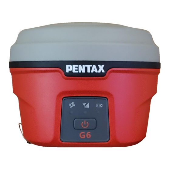
1 Product Information 1.1 G6N Front Panel The front of the G6N has an information panel with 1 power button and 3 LED indicators. Figure 1: G6N Measurements and Front Panel Item Function Upper Housing Cover for GNSS antenna Lower Housing Access for batteries, ports, status panel Satellite LED Blinks for number of satellites tracked... -
Page 4: G6N Ports & Speaker
1.3 G6N Ports & Speaker The ports and speaker are located on the bottom side of the instrument. In addition, the instrument serial number and certification labels are also on the bottom side of the instrument. Figure 3: G6N Bottom Description Function Speaker... -
Page 5: G6 Basic Operation
2 G6 Basic Operation This section highlights the basic operations of G6. 2.1 Power Button The main function of power key is for power on/off and to confirm a selection. Function Button Press Comments LEDs come on & system boots up, position Power On Press for 2 s then release status announcement... -
Page 6: Battery Compartment Door
2.3 Battery Compartment Door The battery compartment latch has a drawing guide indicating the locked and unlocked latch position. The handle is horizontal when locked, and vertical when unlocked. Figure 4: Battery Door Latch 2.4 Nano SIM Card Ensure the instrument is powered Off. The Nano SIM card slot is accessed by opening the battery compartment door. Insert the Nano SIM card into the upper slot, as shown in the guide above the slot, noting the angled edge. -
Page 7: Installing A Battery
2.6 Installing a Battery Figure 6: Battery Latch To install the battery, turn open the battery compartment latch, and the battery compartment door will open upwards. Insert the battery into the battery compartment, the battery latch will lock the battery in place. Close the battery compartment door and lock the battery door latch. -
Page 8: G6N Arp
2.8 G6N ARP The Antenna Reference Point (ARP) is at the bottom of the G6N. The Antenna Code is TIAPENG6. Figure 7: G6 Dimensions 2.9 Antenna Height When using the G6N as a Rover, the antenna height is the vertical height of the survey pole. This is direct to the ARP, so no offsets are required for a vertical survey pole. -
Page 9: Bluetooth Id
Figure 9: Slant Height Adapter Mounting Location Figure 10: Slant Height Measurement When measuring Slant Height from the ground to the end of the Slant Height Adapter, the Vertical Height can be calculated as shown in the figure above. 2.10 Bluetooth ID Bluetooth communication is typical for data collection. -
Page 10: Web Ui
3 Web UI The G6 has an on-board Web UI that is accessed via Wi-Fi. A smart phone, tablet, data controller, PC and similar devices with a web browser can be used to connect the G6 via WI-FI. The G6 WI-FI does not have the Internet access, so only the Web UI pages are viewable. -
Page 11: Status
3.1 Status The Status webpage displays a summary of the current GNSS positioning for a fast confirmation. The webpage displays the System Mode, GNSS position, Position Mode & Latency, Satellites used, DOPs, GNSS Time and the Current Datalink used for differential corrections. There is a button to quickly Disconnect/Connect the datalink. Figure 13: G6 Web UI –... -
Page 12: Satellites
3.3 Satellites The Satellites webpage displays the tracked satellites and allows setting the Cutoff Angle (elevation mask) to limit tracking to satellites below this angle. There is a display choice of display between a Table and a Skyplot. Figure 15: WebUI – Satellites - Table Page | 12... -
Page 13: Download
Figure 16: WebUI - Satellites - Skyplot 3.4 Download The Download webpage displays the raw data files recorded on the G6, with buttons to Download, Delete or Convert a file. The files may be downloaded individually by using the Download button or combined using the Package button when multiple files are selected. -
Page 14: Management
3.5 Management The Management webpage allows the user to Install New Firmware, Register the G6N, Register the GNSS, set/change Password, view logs, Format the SD card, Self-Test, Restore Factory Settings, and Reset the receiver. Figure 18: Web UI – Management Option Description Select the Choose File button, select the Pentax firmware file, then click... -
Page 15: Settings
3.6 Settings The Settings sections allows for user configuration of the G6N. This is presented in three sections by tabs: • Working Mode • Device Configuration • NMEA Message Each section is further discussed below. 3.6.1 Working Mode This Working Mode menu allows the user to select a System Mode as a Base, Rover, or Static. Each mode is unique and different settings will be displayed for user selection and input. - Page 16 3.6.1.2 Rover Mode When the System Mode is Rover, the user can apply the desired configuration for Rover operation. The Rover option allows the user to select a datalink for RTK corrections input. Each datalink selection requires further configuration. The G6N’s further configuration requirements for RTK are shown in the table below for UHF, Network, External and Bluetooth options.
- Page 17 3.6.1.3 Base Mode When the System Mode is set to Base, the user can select options for the Base receiver operation. Base configurations also allow the user to select a datalink for RTK corrections output. The Base datalink configurations are similar to the Rover, and a Base allows the Dual option to output corrections on both UHF and Cellular datalinks.
-
Page 18: Device Configuration
3.6.2.3 Direct Link Mode Direct Link Mode allows for troubleshooting features for EGS to assist. The options allow for tracker and remote debug logging options to verify if an issue is hardware related. The options for Direct Link Mode are: •... -
Page 19: Nmea Message
3.6.3 NMEA Message This allows for NMEA Messages to output through the 5-Pin Lemo cable. The user may select the message and the output frequency. Current messages supported are: • • • GEDOP • • • GEREF • • • GESNR •... -
Page 20: Relay Mode
3.6.4 Relay Mode The Relay mode feature on a G6N rover uses the integrated cell modem to receive differential corrections and relay these corrections over the integrated UHF radio. This mode allows for several G6N rovers to operate in the field while utilizing only one activated SIM card plan. - Page 21 3.6.4.4 Enable Relay Mode From Settings > Working Mode, select ‘Enable Relay Mode.’ Figure 28: Enable Relay Mode 3.6.4.5 Configure the Integrated UHF Radio Select the preferred UHF radio configuration and save the settings. 3.6.4.6 Configure Additional Rovers to receive corrections via UHF radio On another G6N Rover, select the datalink as UHF and set the UHF to receive corrections.
-
Page 22: G6 Standard Accessories
4 G6 standard accessories 4.1 Shipping Case Each G6N comes attractively packaged within a rugged case with all the necessary accessories included. There are two packages offered and thus two differently packed shipping cases: Base and Rover. The Base shipping case comes with room to fit an external radio whereas the Rover shipping case comes with room to fit a data collector. -
Page 23: Uhf Antenna
4.5 UHF antenna The G6N comes with a 4dBi gain UHF antenna. For the US, the 450 – 470MHz variation is included. Figure 31: UHF Antenna 4.6 Accessories The remaining accessories included in the G6N Shipment are shown below. Item Image Description Use this when using UHF... -
Page 24: Appendix 1 Default Radio Configuration
5 Appendix 1 Default radio configuration The frequency and protocol of the default 8 channels can be modified via Web UI or controller. Channel Frequency Protocol 441.00 Trimtalk 4505 442.00 Trimtalk 4505 443.00 Trimtalk 4505 444.00 Trimtalk 4505 445.00 Trimtalk 4505 446.00 Trimtalk 4505 The UHF radio has a frequency range from 410MHz to 470MHz, split into 3 optional bands:... -
Page 25: Appendix 2: Voice Messages
6 Appendix 2: Voice Messages Voice Messages Description Rover Announces “rover” if the current working mode is rover. Base Announces “base” if the current working mode is base. Static Announces “static” if the current working mode is static. Single Announces “single” when the solution is single, or autonomous. Announces “rtd”... -
Page 26: Appendix 3 G6N Specifications
7 Appendix 3 G6N Specifications G6N Specifications Number of Channels GNSS Constellations GPS, GLONASS, Galileo, BeiDou, QZSS & SBAS L1 C/A, L1C, L2C, L2P, L5 GLONASS L1 C/A, L2C, L2P, L3, L5 BeiDou B1, B2, B3 Galileo E1, E5 AltBOC, E5a, E5b, E6 Signal Tracking QZSS L1 C/A, L1C, L2C, L5, L6...
Need help?
Do you have a question about the Pentax G6N and is the answer not in the manual?
Questions and answers