Table of Contents
Advertisement
Quick Links
Advertisement
Table of Contents

Related Manuals for AST RESEARCH SixPakPlus

Summary of Contents for AST RESEARCH SixPakPlus
- Page 1 Monuo User's ASl'nesenncn...
- Page 3 SixPakPlus Card Memory Expansion Personal Computer, Pc-XT, Other Machines IBM-Compatible User's Manual 000123—001 June, 1983 AST RESEARCH. INC. Irvine, California 863—1333 (714)
- Page 4 Compaq is trademark Compaq Computers. Inc. SixPakPlus, SuperPak. SuperDrive, and SuperSpool are trademarks AST Research, © Copyright 1983 AST Research. Inc. All rights are reserved, including those reproduce this book parts thereof any form without permission writing from AST Research. Inc.
-
Page 5: Table Of Contents
“Below” 2.3.1 Installing Card ........ the SixPakPlus ..“Above" 2.3.2 Installing Card the SixPakPlus ..2.4 Installing Additional Memory on the SixPakPlus 2—9 ....2.5 Troubleshooting Memory Problems 2-11 ......PORT SECTION SERIAL ..... 3.1 Configuration of the SixPakPlus Serial P011 .... - Page 6 5.6 Technical Information ....5.6.1 Clock-Czflendar Interrupt Generation ....SECTION GAME ADAPTER PORT ..6.1 Configuration the SixPakPlus Game Adapter Port ......6.1.1 Installing the Cable ....6.1.2 Disabling the Game Adapter Port ....... 6.2 Software Compatibility ........ 6.3 Technical Information ....
- Page 7 Patches for Specific I/O Problems Appendix FIGURES ...... SixPakPlus Board Layout Figure 1»]l Figure 2-1. Starting Address Settings rrrrrrrrrrrrrrrrrrrrrr ....SixPakPlus Memory Size Settings 2-2i Figure ....Parity Check Enable Setting 2-3i Figure ..... 24‘ PC-l System Board Switch Settings Figure .....
- Page 8 (This page intentionally lefi blank)
-
Page 9: Section 1 General Overview
The AST a flexible and powerful multifunction Sixl’akPlusTM is enhancement product for IBM Personal Computer (PC) family. The SixPakPlus provides memory expansion upgradeable maximum addressable user memory new PC and PC-XT in the also powerful data I/O accessory; standard features It is systems. -
Page 10: Standard Features
COM]. Section this manual contains the necessary reconfiguration instructions. Standard features The following are standard features of the SixPakPlus: memory. RS-232C Serial interface to be used with a modem, serial printer, remote display terminal, or other serial... -
Page 11: Available Options
Available options The following options are provided: Memory Expansion available 64K increments up to 384KB. The 384K on the SixPakPlus added to 256K on or PC-XT system board provides 640K, the PC—2 maximum addressable user memory for these systems. Each 64K upgrade consists one AST P/N MP—009... -
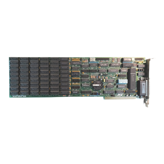
Page 12: Sixpakplus Board Layout
SixPakPlus card to function properly. NOTE sure to fill out your warranty card and mail it in. - Page 13 5:539:80 Ummmfim ._wnE:—. :EEU. 59.005500 x005 5323 item. Enacw Gumtflurz 55250 39:2. 9.50. ton. m... zozsw 52:1 5222; 8.09.50 ESE—.9230 _m__a_mm.m_.. 5.36 >3sz x005 2295 59:3. ten. xzmm 2:6, SixPakPlus Board Layout Figure 1-1.
- Page 14 (This page intentionally left blank)
-
Page 15: Configuration
MEMORY CONFIGURATION order the memory your SixPakPlus card. you must to use properly configure both the SixPakPlus board the PC system board. Subsection 2.1 covers configuration of the switches on the SixPakPlus. Subsection 2.2 describes configuration the system board switches. The system board configuration process varies,... - Page 16 2.1.1 SixPakPlus Starting Memory Address The SixPakPlus card must be properly configured to indicate the memory installed below it, or other words, what amount starting address should Positions Switch #1, the through Memory Configuration Switch, are used to the SixPakPlus’...
- Page 17 PC-XT: When installing the SixPakPIus PC»XT, configure the in a SixPakPIus‘ starting address to the setting which Figure the amount memory installed on the PC-XT corresponds system board. Notice that the SixPakPIus automatically begins limiting the amount of usable memory on the card when starting address configured at 320K or higher.
-
Page 18: 2.1.3 Parity Check Enable
Note that when the starting address (see Topic 2.1.1) 320K or higher, the SixPakPlus automatically begins limiting the amount usable memory the card. This prevent conflicts with areas is to of memory reserved for the monochrome or color display cards. - Page 19 To determine the correct system board switch setting, add PC»1‘ together the amount of memory on the system board (64K) amount of memow on the SixPakPlus, Set the PC-l system board Switch to the corresponding total from Figure 2—4, Notice that the system board switches for...
-
Page 20: Pc~1 System Board Switch Settings
SixPakPlus. Use the appropriate total amount from Figure Please note that when you include memory on the 2—5. SixPakPlus in this total, that your system board must be fully [’02 populated with 256K. system board does not contain your... -
Page 21: Installing Multiple Memory Cards
SixPakPlus. The PC-X'I‘ will automatically recognize the expansion board memory, and... -
Page 22: Installing A Card "Below
Card “Below” 2.3.1 SixPakPlus Installing If another memory card be addressed “below" is to SixPakPlus, then you should follow the procedure listed below. STEP instructions supplied with the other card, configure Following ”above” to reside immediately the memory system board. - Page 23 STEP system board switches for the total amount memory including the system board, the SixPakPlus, and the other card. 2.4 Installing Additional Memory the SixPakPlus SixPakPlus configured with less than 384K maximum memory can be upgraded...
- Page 24 There are five steps to follow when adding memory to the SixPakPlus, STEP off the power Shut and remove the SixPakPlus from to the PC system unit. STEP Install each additional 64K memory chips nine next consecutive empty bank card. For example. referring on the 1-1.
-
Page 25: Troubleshooting Memory Problems
4020 fifth bank actually P01. system. If have error code would this pointing to SixPakPlus; Bank system board. followed Bank 4 0 is on the Banks thru SixPakPlus. 6 on the If you have don‘t confuse bank numbering scheme used PCAZ. - Page 26 have socket, you problem with the board; contact your dealer for assistance. the third and fourth digits code do not match error values indicated Figure you may be experiencing errors 1—], with more than one memory chip. This could be due incorrect switch settings, multiple bad memory chips, or even something as simple as...
-
Page 27: Section 3 Serial Port
PC to a your RS-232C interface. The SixPakPlus interface is a DTE type (Data Terminal Equipment) with male D825 connector. Configuration of the SixPakPlus Serial Port allows installation IBM PC computer of two serial up to ports. called COMl COM2. The serial port your SixPakPlus been configured... - Page 28 SixPakPlus expects that connected device be driving will all its however, your serial device does inputs, not drive the SixPakPlus inputs. you can RS»232C Interface Configuration Jumper card Block on the cause “Forced True" state The following three inputs...
- Page 29 Appendix A, many of the wiring port diagrams for various printers show two or three pins jumpered at the SixPakPlus end of together cable. If you follow these diagrams, you should leave the shorting plugs on the card “Normal"...
- Page 30 3.1.3 Port Disabling the Serial serial port on the SixPakPlus completely disabled can be removing both of shorting plugs referred Figure 3-1. This to in “1“ “2“ means that either would be shorting plugs “35" removed from Port Enable Jumper Block.
- Page 31 If this eliminate this step so. you can well. Serial I/O Port and Pinouts Assignments The serial port SixPakPlus uses on the following system I/O IRQ interrupt request lines: ports Port 1/0 Ports Configuration Line COMl...
- Page 32 Advanced Diagnostics supplied with diagnostics. preferably Hardware Maintenance Manual. the IBM For proper operation of device which you diagnostics. connected have SixPakPlus serial port. to the modem or such as a serial disconnected. Also. printer. must be make that the CTS.
-
Page 33: Section 4 Parallel Printer Port
IBM/Epson MX-SO. This port completely compatible with the IBM PC and uses the same female D825 connector as an IBM port. Configuration of the SixPakPlus Parallel Port The IBM PC allows installation in the up to three computer... -
Page 34: Installing Multiple Parallel Ports In A Pc
LP'I‘l (excluding the IBM Monochrome Display / Printer Adapter card—see next topic), then you must change either the other card or the SixPakPlus to respond as LP'I‘2. This necessary to avoid conflicts between the two ports. - Page 35 SixPakPlus, while the cable from the printer plugs into the D825 connector at the opposite end. With the SixPakPlus installed in the PC, route the rectangular connector on parallel cable through the opening in the SixPakPlus 18”...
-
Page 36: Parallel Port
Port I/O Port 4.4 Parallel Assignments and Pinouts The parallel port on the SixPakPlus uses the following system I/O ports: PORT CONFIGURATION I/O PORTS LPT1* 378-37A Hex LPT2* 278-27A Hex and LPT3 respectively when the IBM Monochrome Display *LP'I‘Z card used. - Page 37 Port Testing of the Parallel Diagnostic Unlike some other multifunction cards, the parallel port on your competely compatible with the IBM Diagnostics. SixPakPlus order for the port to be recognized by the diagnostics, However, LPTl. must be configured you run the Matrix Printer test, your printer must be 100% or errors will be generated.
- Page 38 (This page intentionally left blank)
-
Page 39: Configuration Of The Sixpakplus Clock-Calendar
SECTION THE CLOCK-CALENDAR comes standard with your SixPakPlus and has Clock—Calendar following features: advanced microprocessor 24-hour clock, maintained in an SixPakPlus board on the chip Four-year calendar leap year) Battery backup power supply (battery life. approximately year) User»replaceable Lithium battery Full PC-DOS compatibility. - Page 40 The Clock-Calendar can be completely disabled removing the shorting plug shown Figure 5-1. This may be necessary cases conflict between the ports used by the SixPakPlus clock (reference Subsection 5.6) and other devices installed your PC. The ASTCLOCK Utility: Setting the...
- Page 41 SixPakPlus clock chip until the time and date values stored you execute the procedure below. STEP A> diskette that leaves the screen at the Boot the system with prompt.
- Page 42 DATE values. Diskettes 5.4 Preparing Your Working After installing your SixPakPlus card, you must prepare your working DOS diskettes to automatically initialize the time and date each time that you boot the system. This subsection lists the process used to invoke your Clock-Calendar.
- Page 43 The more the PC is in powered by the PC last. The clock chip on your SixPakPlus on. The battery used as backup power system when your PC off. To replace the battery, slightly lift the while your PC retaining clip with your finger (or a small screwdriver) and use...
-
Page 44: Time And Date
5»1 programming functions and locations. breakdown Generation Clock-Calendar Interrupt 5.6.1 The Clock-Calendar feature of SixPakPlus does not normally writing your own software. however. need or support interrupts. generate timed interrupts SixPakPlus possible program IRQ4, IRQS, or IRQ7 interrupt lines. To... - Page 45 Addressing Clock-Calendar Chip Table 5—1. Function Address seconds counter-l/IOOOO counter-U100 and 1/10 seconds counter-seconds counter-minutes countephours the week counter-days the month counter-day counter-month RAM-upper nibble only RAM-last month storage storage (-80) RAM—year RAM—reserved RAM-not used RAM-not used RAM-not used RAM-not used interrupt status register interrupt control register counter reset...
- Page 46 Figure 5-2 indicates the location relate to the clock interrupts. You should not enable the SixPakPlus clock interrupt feature unless written your own software to handle the interrupts and you have that the IRQ line that you have selected does not (2) double—checked...
-
Page 47: Section 6 Game Adapter Port
SECTION GAME ADAPTER PORT This section describes the optional Game Adapter port for the SixPakPlus card. One IBM-compatible joystick may be used conjunction with this port. Configuration of the SixPakPlus Game Adapter Port of the required parts must game hardware,... -
Page 48: 6.1.1 Installing The Cable
J3 at does not interfere with installation back toward the bottom cover, Adapter Port 6.1.2 Game Disabling The Game Adapter port on the SixPakPlus card can completely Subsection 6, jumper discussed disabled removing... -
Page 49: Software Compatibility
Software Compatibility totally software<eompatible with IBM game The game port adapter when using IBM-type joystick. NOTE Since there are always variations among function joysticks, some software may not IBM-type joystick when an properly. even being used, Therefore. AST suggests that that only quality software and make... - Page 50 above program, moving the joystick When running “X1" readout, while in the X-plane (left-right) causes change moving the joystick in the Y-plane causes change (up—down) “Y1" switch (either one or two, readout. Pressing “SI" ”S3" your joystick) causes a change depending the quality readouts from...
-
Page 51: Section 7 Installing Your Sixpakplus Card
Remove that save flathead screwdriver, Remove the bracket. a small screw using STEP Install the plastic card guide supplied with the SixPakPlus on the of the front panel of the PC. inside STEP from bottom corner your SixPakPlus card Line... -
Page 52: Testing The New Installation
STEP the rear cut-out above keyboard connector your the cards panel, route the adapter cable(s) under out to removed easily cut-out. The cubout‘s plastic cover can “D" towards the rear. You can also install the pressing unused PC slots. supplied extra brackets in the connectors STEP... - Page 53 Del). The ASTCLOCK simultaneously display the current time and date. In program should come up and clock should give the correct time with most cases exception SETCLOCK program set/reset of time zone differences. Use the clock your SixPakPlus.
- Page 54 (This page intentionally left blank.) 7—4...
-
Page 55: Section 8 User Upgrade Information
Game Adapter Order part number SPK-OOOG cable. which consists two [Cs and NOTE Although the AST SixPakPlus card designed for easy user expansion, the warranty coverage the board as applies only to configuration originally shipped from the factory. The... - Page 56 (This page intentionally left blank.)
- Page 57 APPENDIX RECONIMENDED SERIAL PORT CABLING This section contains pin connections and wiring configurations for interfacing the serial port on your SixPakPlus to specific serial printers and modems. For information on wiring other product this manual and your serial interfaces, consult Appendix device‘s manual, or call your printer manufacturer and tell them...
- Page 58 PC that its receiving This wiring allows the printer full. Use a D3255 (female/socket) connector for the buffer (male/plug) for the printer. SixPakPlus serial port and a DBZSP printer like the NEC 7720 (which requires a you have DBZSS), an adapter to hook up the port.
- Page 59 This wiring does not should work with most CRTs and some printers. Use however, DB25P (female/socket) for the SixPakPlus serial port and DBZSS most cases). Notice that (male/plug) for the CRT or printer on the CRT side can be wired together.
- Page 60 Suggested wiring for the Diablo 620 printer: Diablo 620 SixPakPlus Port Port Serial Serial Connector Connector side of the inform This arrangement allows the Diablo the PC interface that receive buffer full. Notice that pins 8 on PC side are wired together, and then commonly connected to pin 20 on the Diablo 620 side.
- Page 61 Epson MX-80 serial Suggested wiring for the Smith-Corona TP—l, printer, and IDS Prism serial primers: Printer SixPakPlus Port Port Serial Connector Connector ——————————————————————————————— ——————————————————————————————— ——————————————————————————————— ——————————————————————————————— (TP-l only) ——————————————————————————————— IDS only) (MX—80. —————————————————————————————— 6 & 8 & ——————————————————————————————— & 8 & 20 ('I‘P-l only) ———...
- Page 62 (This page intentionally left blank)
- Page 63 APPENDIX SWITCHING BETWEEN LPT2 LPTl the .BAT mode to direct The following program can be used primer output, normally designated for the device attached to port the device attached to port LPT2. routed to instead LPT], (The program also directs output, normally designated for the the device port LPT2, to instead be routed device attached...
- Page 64 shown below. The comments LPTSWAP BASIC program, the actual are included for clarification and need not included program: SEG=&H40 finds port address table ‘ A=PEEK B=PEEK save LPTI address (8): ‘ POKE 8,PEEK POKE (10): (ll) PEEK LPTl address LPTZ ll,B POKE POKE...
- Page 65 APPENDIX WIRING RS-232 SERIAL INTERFACES This appendix concerns the wiring of your SixPakPlus Serial communications port to remote devices using the electronic industry association RS-232C standard interface. interfaces to ensure that AST Research carefully designs its RS»232 PC’s operating system software...
- Page 66 For asynchronous applications such as your SixPakPlus Serial communications port, we are interested “states” of only eight or nine (of the twenty»five possible) wires between the DTE (your serial port) and the DCE modem or serial printer DCE port), Let’s look ideal up first...
- Page 67 Terminal to modem Ideal: Side Modem Side Pin # Signal Signal Ground Ground Ground Ground (RI) (Hi) DTFl Interface Case: DTE to DCE Ideal Figure Notice that the INPUT signals on the DTE side of the interface are DCD, DSR, CTS, and RxD. Also, die DTE has OUTPUT DTR, and RTS.
- Page 68 One other concept: you can think certain pins on one side of the interface as being “functional When the AST serial port pairs”. sends DTR, it expects to see DSR (and DCD) raised response. DTR and DSR are signal and response to one another. For this think of diem a pair.
- Page 69 Ground Ground Ground DTFl Interface Typical (Non-Ideal) Case: DTE to DCE Figure contains another example of interfacing a serial Figure PC's SixPakPlus card Serial to the port. printer to Send line 19, a Secondary Request In this printer uses case, oddity, careful examination 4.
- Page 70 Series Port 7700 Serial Serial Printer Series 7700 Serial Printer Side Port Side Pin # Signal Signal Ground Ground Ground Ground ‘ SFlTS Printer Interface C-3. DTE to NEC 7700 Figure other of the interface. When sequence important, this side good way to tell whether or not your interface work.
- Page 71 Your SixPakPlus Serial communications port end requires a DBZSS, female or socket type connector. To properly wire your serial interface signals, suggest you Figure C-4 as aids the form shown design you have several different serial devices which will Hint:...
- Page 72 (This page intentionally left blank)
- Page 75 LIMITED WARRANTY this warrants to the purchaser original Research, Inc. order product that good working Research, Inc. from the date purchase from period of year dealer. Should Research, Inc. or an authorized Research, Inc. opinion, malfunction during Research, Inc's this product, replace its option, repair or the warranty...
- Page 77 PRODUCT REPAIR PROCEDURE Research product ever requires repair, contact your whom your dealer The dealer first. from you originally purchased the product can usually service the product. must return a hardware product to the factory service, these accurate turnaround: guidelines to ensure follow rapid,...
- Page 78 Parts not covered under the warranty: Dealer- chips) user-installed parts (such the warranty. Dealer- covered under the terms warranted the dealer; parts installed parts the parts covered that you install only by that your dealer- suppliers‘ warranties. we find defective, we can identify user-installed parts not replace...
- Page 80 000123-001 5/84...
Need help?
Do you have a question about the SixPakPlus and is the answer not in the manual?
Questions and answers