Table of Contents
Advertisement
Quick Links
Advertisement
Table of Contents

Summary of Contents for aptos MAC DTU
- Page 1 Version 1.0 (August 2021)
-
Page 2: Table Of Contents
4.6 Install the DTU..............................10 5. Complete Installation Map............................12 6. Site Creation on HMP..............................13 7. Customer Login................................14 8. Browse the Web Station............................14 9. View Phone APP................................. 15 10. LED Indicators................................15 11. Technical Data................................16 © 2021 Aptos Solar Technology, LLC. All rights reserved. -
Page 3: Important Safety Information
Note that only professionals can install or replace DTU. Do not try to repair DTU without approval from Aptos. If DTU is damaged, please return to your installer for repairing/replacing. Disassembling DTU without approval from Aptos will invalidate remaining of the warranty period. -
Page 4: Other Information
2.2 DTU The DTU is the key component in Aptos microinverter system. It works as the communication gateway, which operates between the Aptos microinverters and the Aptos Monitoring Server. The DTU communicates with the microinverter wirelessly via 2.4GHz Proprietary RF (Nordic), collecting the operation data of the system. -
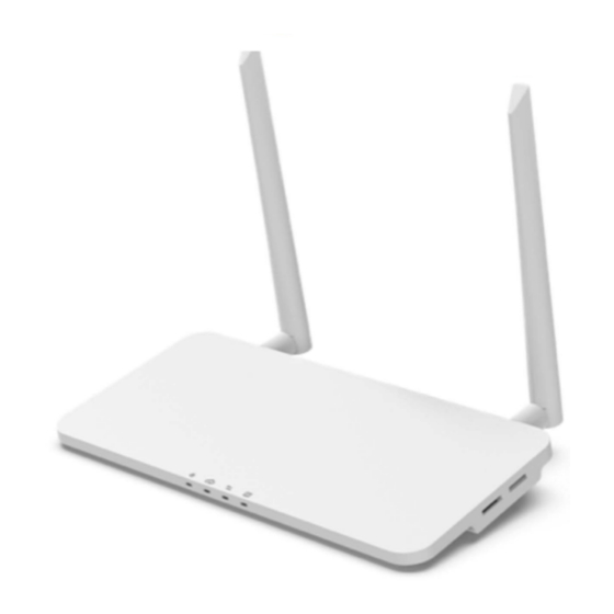
Page 5: Interface Layout
DTU Alarm Indicator WiFi Antenna (2.4G) RS485 DRM Port (For Australia only) Ethernet Port USB Port Reset Bottom Power Port 2.4G Antenna 3.2 Export Management Function (RS485 port) a. Device Required. © 2021 Aptos Solar Technology, LLC. All rights reserved. -
Page 6: Remote Active Power Control (Rs485 Port)
MAC 800R MAC 800R MAC 800R Note: Please refer to “Aptos Export Management Technical Note” for more details. 3.3 Remote Active Power Control (RS485 port) Some countries require generating plants to be equipped with a logic interface (input port) in order to cease output active power or limit active power to a regulating level. -
Page 7: Local Install Assistant
DTU installation, and avoid a second visit by the installler due to a poor connection between DTU and certain MI. Please refer to “Aptos Local Install Assistant Technical Note” for more details. Note: © 2021 Aptos Solar Technology, LLC. All rights reserved. -
Page 8: Dtu Installation
The temperature should be between -20ºC and 55ºC. If you plan to install the DTU on the wall, please prepared two #8 (4.166mm diameter) screws and a screwdriver in advance. 4.3 Dimensions © 2021 Aptos Solar Technology, LLC. All rights reserved. -
Page 9: System Installation Sequence
8. Check the Communication 3. Connect to the Internet between Microinverters and DTU 4. Start procedure 9. Wall-mount the DTU (optional) 5. Normal operation 4.5 Preparation Download the Aptos mobile App © 2021 Aptos Solar Technology, LLC. All rights reserved. -
Page 10: Install The Dtu
Note:If the DTU installation location is inside the metal box or under the metal / concrete roof, extended 2.4G cable or 2.4G sucker antenna will be suggested, which can be purchased from Aptos or local electrical store (Please contact Aptos Tech. support team for the detail type of the cable or antenna at info@aptossolar.com ). - Page 11 Please make sure the antennas are vertical to the wall. Option 2: Place the DTU on the table - Place DTU on the table. Ensure the antennas are vertical to the table; © 2021 Aptos Solar Technology, LLC. All rights reserved.
-
Page 12: Complete Installation Map
“Network Configuration”, select “Ethernet” (for Ethernet option). 5. Complete Installation Map Please complete the installation map. Peel the serial number label (as circled below) from the DTU and place it on the installation map. © 2021 Aptos Solar Technology, LLC. All rights reserved. -
Page 13: Site Creation On Hmp
Complete system information of the installation map shown as follows. 6. Site Creation on HMP A. Install Aptos Installer APP by searching “Aptos” at the App Store (IOS) or Play Store (Android). B. Open the APP and login in with your installer account name and password. If you are a new installer with Aptos, please apply an Installer account from your distributor in advance. -
Page 14: Customer Login
M.Please wait about 30 minutes, the station will show online, and all the MI-IDs are found. 7. Customer Login Please download the End User App. You can search “Aptos” at the App Store (IOS) or Play Store (Android). Log in with the Password and Username that has been set up by Installer on the previous step (Section 6, step e), and press “Login”. -
Page 15: View Phone App
9. View Phone APP Download mobile phone application to view station information 10. LED Indicators The system status can be viewed by Aptos local APP or LED indicators. LED Color Explanation mark DTU power on or power off Network communication... -
Page 16: Technical Data
Per 15 minutes Communication to Meter Signal RS485 Maximum distance (RS485 cable) 500m Display LED Indicator * 4 – RUN, Cloud, MI, ALM Local APP Power Supply Type External plug-in adapter © 2021 Aptos Solar Technology, LLC. All rights reserved. - Page 17 *1 If the DTU installation location is inside the metal box or under the metal/concrete roof, extended antenna will be suggested. *2 Depending on the installation environment, please refer to user manual for more details. © 2021 Aptos Solar Technology, LLC. All rights reserved.
Need help?
Do you have a question about the MAC DTU and is the answer not in the manual?
Questions and answers