Table of Contents
Advertisement
Quick Links
Advertisement
Table of Contents

Related Manuals for Muller 6609d


Summary of Contents for Muller 6609d
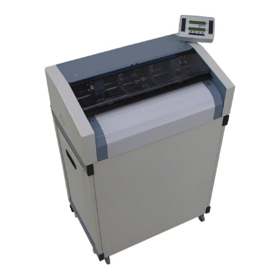
- Page 1 Service Instructions Automatic Forms Cutter Modell 6609d-6612d Stand: 31.05.2006...
-
Page 2: Table Of Contents
Mod. 6609-12d: Automatic Forms Cutter 31.05.2006 Contents Tool list ................3 EG-Konformitätserklärung . -
Page 3: Tool List
Mod. 6609-12d: Automatic Forms Cutter 31.05.2006 Tool list A tool case is available which contains all the tools listed below: Part no. Decription Size No. each 10580 Cable tie 10893* Pin (for installing the pulley of the cross cutter) 10897 Feeler gauge 10899* Open-ended spanner 10961* Tool for adjusting tractor shaft... -
Page 4: Eg-Konformitätserklärung
Mod. 6609-12d: Automatic Forms Cutter 31.05.2006... -
Page 5: Subassemblies
Mod. 6609-12d: Automatic Forms Cutter 31.05.2006 Subassemblies Housing and cover sheets Frame Driving shafts Frame - motors and fan Safety cover Cross cutter - blade bar Cross cutter - ejector Cross cutter - drive ... -
Page 6: Adjusting Tractor Shaft
Mod. 6609-12d: Automatic Forms Cutter 31.05.2006 Caution: When performing servicing work on the cutter, always make sure it is disconnected from the mains power supply. 1. Adjusting tractor shaft The tractor shaft is divided in the middle. Use the two adjusting tools (tool no. 10961) to rotate the tractor shaft and adjust the angle of the cross cutter. -
Page 7: Tightening The Sprocket Belts
Mod. 6609-12d: Automatic Forms Cutter 31.05.2006 3. Tightening the sprocket belts Tightening the sprocket belts is done by pushing the rear cap bolt. To do so, first take off the cover plate and unscrew the plate . Do not overtighten the sprocket belts (test by hand to make sure they move easily). -
Page 8: Adjusting The Paper Guide (On The Pneumatic Spring)
Mod. 6609-12d: Automatic Forms Cutter 31.05.2006 7. Adjusting the paper guide (on the pneumatic spring) When the plexiglass cover is closed, the paper guide should be about 1 to 1.5 mm from the center bearing block. Remove the screw to move the device for holding down paper onto the gas cylinder . -
Page 9: Removing Scanners On The Tractor And Cross Cutter
Mod. 6609-12d: Automatic Forms Cutter 31.05.2006 Removing scanners on the tractor and cross cutter To remove the scanner on the cross cutter, first take out the entire cross cutter (see 13). The fibre-optic heads on the shafts of the tractor and cross cutter are screwed into a holder. -
Page 10: Cleaning, Installing And Adjusting Scanners On The Tractor Shaft
Mod. 6609-12d: Automatic Forms Cutter 31.05.2006 11. Cleaning, installing and adjusting scanners on the tractor shaft Remove the tractor shaft as described in 9. Clean the encoder disc and scanner head with a soft lint-free cloth. Do not use any cleansing agents. -
Page 11: Removing The Cross Cutter
Mod. 6609-12d: Automatic Forms Cutter 31.05.2006 13. Removing the cross cutter The cross cutter can be removed as a single unit for servicing or replacing. To do so, remove the drive belt and air tube. Lift up the bars. Disconnect both motors of the cross cutter. Open the plexiglass cover. -
Page 12: Removing And Adjusting The Cross Cutter Blade
Mod. 6609-12d: Automatic Forms Cutter 31.05.2006 Removing and adjusting the cross cutter blade Remove the drive belts and air tube. Lift up the bars and open the snap locks. Tilt down the entire ejector unit. Move the upper blade to its maximum position by hand. Reduce spring pressure of the lower blade. -
Page 13: Adjusting Spring Pressure Of The Lower Blade On The Cross Cutter
Mod. 6609-12d: Automatic Forms Cutter 31.05.2006 Adjusting spring pressure of the lower blade on the cross cutter Tilt down the ejector unit (see 14). Turn the screws , to adjust spring pressure of the lower blade . This pressure must be set correctly to ensure top cutting performance. -
Page 14: Removing And Adjusting The Blade Guide Bar
Mod. 6609-12d: Automatic Forms Cutter 31.05.2006 17. Removing and adjusting the blade guide bar Blade guide bars can only be exchanged as entire units (see list of exchange parts). The guides are removed and replaced at the factory. Tilt down the ejector unit (see 14). Remove the screws . -
Page 15: Removing The Driving Gear On The Cross Cutter
Mod. 6609-12d: Automatic Forms Cutter 31.05.2006 19. Removing the driving gear on the cross cutter Completely remove the cross cutter (see 13). Tilt down the ejector unit. Remove the Seeger circlip ring. To remove the belt pulley of the cross cutter, remove the three screws which can be accessed through the hole in the belt pulley itself. -
Page 16: Removing The Blades Of The Edge Cutters
Mod. 6609-12d: Automatic Forms Cutter 31.05.2006 22. Removing the blades of the edge cutters Remove the drive shaft as described in 9. Unscrew the paper guide . Loosen the screws by turning them 1-2 rotations and remove the housing plates . Take off the washer . Completely remove the edge cutter from the block . -
Page 17: Removing The Terminal Board And Replacing The Eprom
Mod. 6609-12d: Automatic Forms Cutter 31.05.2006 23. Removing the terminal board and replacing the eprom Undo the four screws on the bottom of the terminal . Push the terminal forward to remove it. Disconnect the plug. Terminals can only be exchanged as entire units (see list of exchange parts). -
Page 18: Main Pc-Board Connections
Mod. 6609-12d: Automatic Forms Cutter 31.05.2006 26. Main PC-Board connections 27. Removing the main board Lift the plexiglass cover. Disconnect all plugs. Remove the eight knurled screws. Pull the board 5 cm forward. Use the lever (tool no. 15336 - ) to disconnect the fibre-optic plugs - do not disconnect it by pulling on the cable . - Page 19 Mod. 6609-12d: Automatic Forms Cutter 31.05.2006 -19-...
-
Page 20: Main Pc-Board Installation
Mod. 6609-12d: Automatic Forms Cutter 31.05.2006 Main PC-Board installation Please note the following positions, before setting the PCB`s to work! Connect all fibre optic plugs. (Take care beforehand, that plugs and connector sockets are perfectly clean!) Fix all thumbscrews on the PCB tight (due to ground contacts). Insert the ID-chip on the the new PCB (take it from the exchanged board!). -
Page 21: Listing Of All Automatic Forms Cutter Pcb, Being Produced Since 1988
6612 with Chopper one Tractormotor 6612 for use in printing and mailing houses* 6611C 6612C 6609D-6610D 6611D-6612D *Printing and mailing houses: No Waste-Chopper and ejectors are not installed. The power supply is mounted outside the machine -21-... -
Page 22: Measurement-Points-Pc-Board
Mod. 6609-12d: Automatic Forms Cutter 31.05.2006 Measurement-Points-PC-Board -22-... - Page 23 Mod. 6609-12d: Automatic Forms Cutter 31.05.2006 MEASUREMENT-POINTS (Fibre-Optic) at PC-Board 1 ) Analogue-output Amplifier for encoding-disks with running motors: Testpin 1 and 2 Cross-Cutter: Scope square (trapezoid) signal 1V - 11V (start servive routine 011/012, disconnect function of the cutting blade (follow the instructions at chapter 3, Pos.
-
Page 24: Omr
Mod. 6609-12d: Automatic Forms Cutter 31.05.2006 OMR: Testpin 23 (OMR Sensitivity): D C - V o l t a g e , d e p e n d a n t o n sensitivity-level Service 060 level ca. 8,1V ca. 9,0V ca.
Need help?
Do you have a question about the 6609d and is the answer not in the manual?
Questions and answers