Table of Contents
Advertisement
Quick Links
Advertisement
Table of Contents

Related Manuals for Huahuan Electronics H20RN-2000.V2 Series

Summary of Contents for Huahuan Electronics H20RN-2000.V2 Series
- Page 1 H20RN-2000.V2 Series IP/MPLS Aggregation Platforms Hardware Description...
- Page 2 H20RN-2000.V2 Series IP/MPLS Aggregation Platforms Hardware Description Beijing Huahuan Electronics Co., Ltd. Oct.2019...
- Page 3 Copyright Notice The intellectual property rights of all parts of this product, including accessories etc., are owned by Beijing Huahuan Electronics Co., Ltd. (Beijing Huahuan for short). Without prior written consent of Beijing Huahuan, no part of this document may be reproduced or transmitted in any form or by any means.
-
Page 5: Table Of Contents
2.3.6 Protection Ground Cable (ZJN.BH4.851.134) ............24 2.3.7 Dual-E1 Socket Cable....................26 3 Technical Specifications ................. 28 3.1 Monitoring Interface .......................28 3.2 10/100/1000Base-Tx Interface ..................28 3.3 100/1000Base-SX/LX Interface ..................29 3.4 10GBase-SX/LX Interface ....................29 3.5 E1 Signal Interface ......................30 Beijing Huahuan Electronics Co., Ltd. Version 1.3(Oct.2019) -
Page 6: Contents
4.6 16E1 Emulation Card (EC16) ....................36 4.7 STM-1 Interface Emulation Card (SC01QE) ..............36 4.8 Power Card (PWR48150/PWR22150/PWR4875/PWR2275) ...........37 4.9 Power Card (PWR48/PWR22) ..................38 4.10 FAN Card (FAN02/FAN) ....................39 5 Appendix2 Terms and Abbreviations ............40 Beijing Huahuan Electronics Co., Ltd. Version 1.3(Oct.2019) -ii-... -
Page 7: List Of Figures
Figure 2-1 The H20RN-2000.V2 chassis slot allocation diagram ..........2 Figure 2-2 The H20RN-2000L.V2 chassis slot allocation diagram ..........3 Figure 2-3 Front panel diagram of H20RN-2000.V2 series devices .........4 Figure 2-4 Front panel diagram of H20RN-2000L.V2 series devices........4 Figure 2-5 RJ-45 connector pin number diagram ..............6 Figure 2-6 Dual-E1 connector diagram ..................8... - Page 8 Figure 4-14 Power card (~220V AC) ..................38 Figure 4-15 Power card (DC -48V) ..................38 Figure 4-16 Power card (AC ~220V) ..................38 Figure 4-17 Fan card (FAN02) ....................39 Figure 4-18 Fan card (FAN) ....................39 Beijing Huahuan Electronics Co., Ltd. Version 1.3 (Oct.2019)
- Page 9 List of Tables Table 2-1 The H20RN-2000.V2 card configuration list .............2 Table 2-2 The H20RN-2000L.V2 card configuration list ............3 Table 2-3 The LED functional descriptions of H20RN-2000.V2 series IP/MPLS aggregation platforms ..........................5 Table 2-4 RJ-45 socket definition at GE port ................6 Table 2-5 Dual-E1 socket E1 signal pin definition ..............7...
-
Page 11: Overview
H20RN-2000.V2 Series Platforms 1 Overview Overview H20RN-2000.V2 Series IP/MPLS Aggregation Platforms use routing architecture, solve the network smooth evolution, equipment interconnection and interoperability, and realize the end-to-end clock scheme. It supports L2/L3 protocol and builds reliable carrier-level packet switching network. -
Page 12: Architecture And Introduction
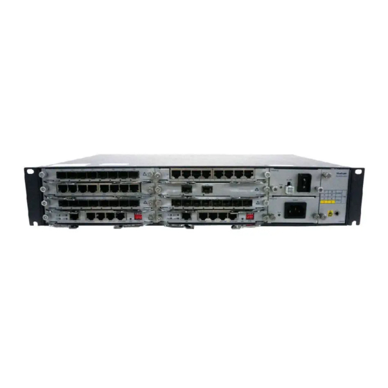
Hardware Description 2 Architecture and Introduction H20RN-2000.V2 Series Platforms Architecture and Introduction 2.1 Configurations H20RN-2000.V2 series IP/MPLS aggregation platforms are composed of cards from aggregation side tributary side, including hot-backup power cards (PWR48150/PWR22150/PWR4875/PWR2275) or (PWR22/PWR48), 2 master-control switching cards (MX01/PMX01), and 1 fan card (FAN02). Tributary cards include 2×10GE interface card (XGE02/XGE02G/TU02), 16E1 emulation card (EC16), STM-1 interface emulation card (SC01QE), 8GE interface card (GE08/GU08/GE08G/ GE08E/GU08E). -
Page 13: Figure 2-2 The H20Rn-2000L.v2 Chassis Slot Allocation Diagram
Slot 2 XGE02/XGE02G 2×10GE card Slot 1, 3, 4 8GE card GE08/GU08/GE08G/G Slot 1, 3, 4 E08E/GU08E 16E1 emulation card EC16 Slot 1, 3, 4 STM-1 interface SC01QE Slot 1, 3, 4 emulation card Beijing Huahuan Electronics Co., Ltd. Version 1.3(Oct.2019) -
Page 14: Architecture
220V power card Slot PWR1, PWR2 Fan card FAN02 Fan slot 2.2 Architecture The front panel diagram of H20RN-2000.V2 series is shown in Figure 2-3 and Figure 2-4. Figure 2-3 Front panel diagram of H20RN-2000.V2 series devices GU08E GE08 GE08E PWR22150 H20RN-2000.V2... -
Page 15: Table 2-3 The Led Functional Descriptions Of H20Rn-2000.V2 Series Ip/Mpls Aggregation Platforms
Hardware Description H20RN-2000.V2 Series Platforms 2 Architecture and Introduction Table 2-3 The LED functional descriptions of H20RN-2000.V2 series IP/MPLS aggregation platforms Mark Color Functional description Green Device running indication (flash frequency 1s): Blink: running normally Off: running abnormally Green Master/standby status indication:... -
Page 16: Device Ports
BI_D BI_D Note: BI stand for bidirectional. Ethernet electrical port of H20RN-2000.V2 series platforms can automatically detect the transceiver line order of the connected network cable and make adaptions. So the port can be used whether the Ethernet interface is MDI or MDI-X and whether the network cable used is crossover or straight-through. -
Page 17: Table 2-5 Dual-E1 Socket E1 Signal Pin Definition
E1 Port On the H20RN-2000.V2 series platforms, EC16 card supports 16 E1 ports whose impedance supoort 75Ω and 120Ω. E1 port uses dual-E1 socket. Each E1 port is corresponding to 2-channel E1. See signal definition in Table 2-5. -
Page 18: Figure 2-6 Dual-E1 Connector Diagram
Table 2-6 E1 port DIP definitions Definition Remark K1_1/K1_2 ON/ON: selects 75Ω in the 1 E1 channel 8-position DIP OFF/OFF: selects 120 Ω in the 1 switches of K1 channel control 1~4 E1 Beijing Huahuan Electronics Co., Ltd. Version 1.3(Oct.2019) - Page 19 ON/ON: selects 75Ω in the 10 E1 channel selections OFF/OFF: selects 120 Ω in the 10 channel K3_5/K3_6 ON/ON: selects 75Ω in the 11 E1 channel OFF/OFF: selects 120 Ω in the 11 channel Beijing Huahuan Electronics Co., Ltd. Version 1.3(Oct.2019)
- Page 20 External Clock Input/output Port MX01/PXM01 card of H20RN-2000.V2 series platforms provides 1-channel of external clock input\output port, supporting 2MHz, 2Mbit/s clock mode. It is marked with “BITS”, using RJ45 socket. RJ-45 connector diagram and pin definition are shown in Figure 2-5 and Table 2-7.
-
Page 21: Table 2-7 Definition Of H20Rn-2000.V2 Series Platforms External Clock Input\Output Ports
CGND External Time Synchronization Port On the H20RN-2000.V2 series platforms, MX01/PXM01 card provides one 1PPS TOD port, with configurable input and output, labeled “1PPS TOD”. It uses RJ45 connector as shown in Figure 2-5, pin definition is shown in Table 2-8. -
Page 22: Figure 2-7 Reset Button
RS-422_2_P TOD time information Reset Button On the H20RN-2000.V2 series platforms, there is a reset button marked with “RST” on the front panel of MX01/PXM01 card, which can reset the system manually, as shown in Figure 2-7. Figure 2-7 Reset button Management Port On the H20RN-2000.V2 series platforms, MX01/PXM01 card provides 1 NM port and 1... -
Page 23: Table 2-10 Rj-45 Socket Definition At Nm Port
Table 2-11 RJ-45 socket definition at Console port Definition DIP Control On the H20RN-2000.V2 series platforms, MX01/PXM01 card provides 1 group of 4-position DIP switches, the definitions of DIP switches are shown in Table 2-12. The “ON” in the table is the ON in the DIP switch. -
Page 24: Fan
2.2.3 Fan In order to improve the whole performance of the system, H20RN-2000.V2 series platforms configure the fan card on the rightmost of the chassis which has 2 round fans in total. H20RN-2000.V2 series platforms support the fan speed detection function, when any round fan works abnormally, fan alarm indicator light will be on, at the same time, and the corresponding alarm will be displayed on the network management interface. -
Page 25: Figure 2-8 Db9-Rj45 Serial Port Cable
PIN6 RxD PIN5 GND PIN5 GND Technical Specifications Table 2-13 lists technical specifications of DB9-RJ45 serial port cable. Table 2-13 Technical specifications of DB9-RJ45 serial port cable Item Description Name DB9-RJ45 serial port cable Beijing Huahuan Electronics Co., Ltd. Version 1.3(Oct.2019) -
Page 26: Fiber And Connector (Lc/Pc)
Introduction Device supports single-mode or multi-mode fiber. Appearance LC/PC fiber connector used by H20RN-2000.V2 series platforms is shown in Figure 2-10. Figure 2-10 LC/PC fiber connector When connecting or removing the LC/PC optical connector, align the connector with the optical port, and do not rotate the fiber. Note the following points: To insert the fiber, align the head of the fiber jumper with the optical ⚫... -
Page 27: Ethernet Cable
Used to connect the Ethernet monitoring interface on NM card with ⚫ network interface on NM PC machine. The Ethernet interfaces on the H20RN-2000.V2 series platforms are self-adaptive to straight-through cable mode and crossover cable mode. Both of them can be used to connect Ethernet electrical interface. -
Page 28: Figure 2-12 Line Order Of The Straight-Through Cable
Brown Brown PIN 8 PIN 8 RJ45 connectors on both ends of crossover cable need to use different standard line orders, usually one RJ45 connector follows EIA/TIA568A standard; the other RJ45 connector follows Beijing Huahuan Electronics Co., Ltd. Version 1.3(Oct.2019) -
Page 29: Figure 2-13 Line Order Of The 100 Mbit/S Crossover Cable
PIN 7 Blue White/blue Brown PIN 8 PIN 8 NOTE 1000Mbit/s crossover cable uses all 8 pins. The crossover is PIN1 to PIN3, PIN2 to PIN6, PIN4 to PIN7, and PIN5 to PIN8. Beijing Huahuan Electronics Co., Ltd. Version 1.3(Oct.2019) -
Page 30: Ac Power Cable
AC power cable transports AC power from power distribution equipment to AC power supply socket, and then transmits power to the entire device. The selections of AC power cables are different according to local standards, as shown in Table 2-16. Beijing Huahuan Electronics Co., Ltd. Version 1.3(Oct.2019) -
Page 31: Figure 2-15 Chinese Standard Ac Power Cable (Bh4.855.035-A)
The AC power cable which meets German standard is composed of German standard French-mode two-plug connector and pins terminal, as shown in Figure 2-16. Figure 2-16 German standard AC power cable (BH4.855.035-B) The AC power cable which meets American standard is composed of American standard Beijing Huahuan Electronics Co., Ltd. Version 1.3(Oct.2019) -
Page 32: Figure 2-17 American Standard Ac Power Cable (Bh4.855.035-C)
Figure 2-20 British standard AC power cable (BH4.855.035-F) The AC power cable which meets North American standard is composed of North American standard three-plug connector and pins terminal, as shown in Figure 2-21. Beijing Huahuan Electronics Co., Ltd. Version 1.3(Oct.2019) -
Page 33: Dc Power Cable (Zjn.bh4.855.079)
Appearance The DC power cable is composed of 2×2 connector and power cables, as shown in Figure 2-22. Figure 2-22 DC power cable CGND -48V GND -48V Beijing Huahuan Electronics Co., Ltd. Version 1.3(Oct.2019) -
Page 34: Protection Ground Cable (Zjn.bh4.851.134)
The protection ground cable is composed of wiring terminals and the coaxial cable. The wiring terminal is usually an OT bare-press terminal. The coaxial cable is yellow/green copper burn-resistant cable. Figure 2-23 shows the grounding cable. Beijing Huahuan Electronics Co., Ltd. Version 1.3(Oct.2019) -
Page 35: Figure 2-23 The Grounding Cable Diagram
Table 2-20 Technical specifications of the grounding cable Item Description Cable type Electronic and electrical cable Cable length 0.4 m Color Yellow and green Connector type OT/OT Inner conductor cable Cross-sectional area ≈ 0.75 mm standard Maximum current 7.5 A Beijing Huahuan Electronics Co., Ltd. Version 1.3(Oct.2019) -
Page 36: Dual-E1 Socket Cable
Figure 2-25 Dual E1 socket cable (ZJN.BH4.850.123) diagram RJ45 Pin Assignments Table 2-5 shows pin assignments of dual E1 socket cable. Technical Specifications Table 2-21 shows technical specifications of dual E1 socket cable (ZJN.BH4.850.107). Beijing Huahuan Electronics Co., Ltd. Version 1.3(Oct.2019) -
Page 37: Table 2-21 Technical Specifications Of E1 Cable (Zjn.bh4.850.107)
Table 2-22 Technical specifications of E1 cable (ZJN.BH4.850.123) Item Description Cable name RJ45/BNC connector adapter cable Cable type SYV75-2-1 (diameter: 2mm, coaxial cable) Connector RJ45 crystal head, BNC head Cable length L1=20cm; L2=25cm; L3=30cm; L4=35cm Beijing Huahuan Electronics Co., Ltd. Version 1.3(Oct.2019) -
Page 38: Technical Specifications
10/100Base-T Ethernet MDI interface interface CONSOLE interface RS232 interface Protocol SNMP Connector RJ-45 3.2 10/100/1000Base-Tx Interface Specifications Instruction Interface rate 10M/100M/1000M Interface specifications Complying with IEEE 802.3, IEEE-802.3u, IEEE 802.1Q, IEEE 802.1p Beijing Huahuan Electronics Co., Ltd. Version 1.3(Oct.2019) -
Page 39: 100/1000Base-Sx/Lx Interface
850nm, 1310nm, 1550nm) Optical interface Determined by optical module technical parameters 3.4 10GBase-SX/LX Interface Specifications Instruction Interface Complying with IEEE802.3, IEEE 802.3ae, IEEE 802.1Q, IEEE 802.1p, IEEE802.1ad, IEEE802.1d, specifications IEEE802.1w, IEEE802.3ad, IEEE802.3ah, IEEE802.1ag, Y1731 Beijing Huahuan Electronics Co., Ltd. Version 1.3(Oct.2019) -
Page 40: E1 Signal Interface
Line code format HDB3 Impedance 75Ω unbalanced interface/120Ω balanced interface Connector RJ-45, dual-E1 socket Interface G.703 specification 3.6 STM-1 Opital Interface STM-1 interface specifications Bit rate 155520kbit/s ±4.6ppm Line code format Scramble NRZ Beijing Huahuan Electronics Co., Ltd. Version 1.3(Oct.2019) -
Page 41: External Clock Input/Output Interface
3.7 External Clock Input/output Interface Specifications Instruction External clock 2MHz,2Mbit/s input 2MHz,2Mbit/s External clock output Connector RJ45 socket Interface G.703 specification 3.8 External Time Sychronization Interface Specifications Instruction Electrical RS422 specification Interface RJ-45 socket connector Beijing Huahuan Electronics Co., Ltd. Version 1.3(Oct.2019) -
Page 42: Power Voltage
Specifications Instruction Voltage DC -48V (-36V~-72V) AC ~220V (165V~265V) 3.10 Power Consumption Specifications Instruction Power ≤150W consumption 3.11 Operation Environment Specifications Instruction Operation -5°C~55°C temperature Storage -25°C~60°C temperature Relative 5%~95%RH (non-condensing, non-frost) humidity Beijing Huahuan Electronics Co., Ltd. Version 1.3(Oct.2019) -
Page 43: Chassis Size
Hardware Description H20RN-2000.V2 Series Platforms 3 Technical Specifications 3.12 Chassis Size Specifications Instruction Size H20RN-2000.V2 W×D×H (mm): 443×252×89 H20RN-2000L.V2 W×D×H (mm): 430×254×44 3.13 Device Weight Specifications Instruction Weight ≤7.6kg Beijing Huahuan Electronics Co., Ltd. Version 1.3(Oct.2019) -
Page 44: Appendix1 General Card Introduction
Appendix1 General Card Introduction NOTE For the installation of equipment, please refer to the H20RN-2000.V2 Series IP/MPLS Aggregation Platforms Quick Installation Guide. 4.1 NM+PX Card (MX01) NM+PX card is a master-control switching card, which is inserted into slot1 or slot2. There are four LEDs located on its front panel: RUN, ALM, MA and BUSY. -
Page 45: 2×10Ge Card (Xge02/Xge02G/Tu02)
Figure 4-5 2×10GE card (TU02) XGE1 XGE2 LINK 4.4 8GE Card (GE08/GE08G/GU08) 8GE card provides 8 GE optical ports, each of which has one LINK LED. Figure 4-6 8GE card (GE08) GE08 LINK Beijing Huahuan Electronics Co., Ltd. Version 1.3(Oct.2019) -
Page 46: 8Ge Card (Ge08E/Gu08E)
16E1 emulation card supports transmitting 16 E1 signals, using RJ45 ports. Figure 4-11 16E1 emulation card (EC16) GU08E EC16 10 11 12 13 14 15 4.7 STM-1 Interface Emulation Card (SC01QE) STM-1 interface emulation card (SC01Q) supports 4 STM-1 SFP optical ports. Beijing Huahuan Electronics Co., Ltd. Version 1.3(Oct.2019) -
Page 47: Power Card (Pwr48150/Pwr22150/Pwr4875/Pwr2275)
Power card is used to provide working power and fan power for each card. One appropriate power card is capable of providing the power supply for the whole H20RN-2000.V2 series platforms. In order to improve the device reliability, user can configure 2 power cards to provide 1+1 hot backup. -
Page 48: Power Card (Pwr48/Pwr22)
Figure 4-14 Power card (~220V AC) PWR22150 4.9 Power Card (PWR48/PWR22) Please refer to Power Card (PWR48150/PWR22150/PWR4875/PWR2275) for detailed descriptions. Figure 4-15 Power card (DC -48V) PWR48 DC -48V Figure 4-16 Power card (AC ~220V) PWR22 Beijing Huahuan Electronics Co., Ltd. Version 1.3(Oct.2019) -
Page 49: Fan Card (Fan02/Fan)
User can monitor the fan running state through NMS, if the fan fault alarm is displayed on the network management interface, user needs to detect the fan timely and replace the fan. Figure 4-18 Fan card (FAN) E S D Beijing Huahuan Electronics Co., Ltd. Version 1.3(Oct.2019) -
Page 50: Appendix2 Terms And Abbreviations
Ear hanging is a component located on the side of the chassis, used to install the chassis into the cabinet. Label Label is the Identification for cable, chassis and alarm. Multi-mode Fiber Multi-mode can be transmitted in one fiber Beijing Huahuan Electronics Co., Ltd. Version 1.3(Oct.2019) - Page 51 Protection ground wire is used to connect device Wire with the protection ground. Usually, it is a yellow-green coaxial wire. Abbreviations Alternating Current Direct Current Electro Static Discharge Fast Ethernet Gigabit Ethernet International Electro technical Commission Beijing Huahuan Electronics Co., Ltd. Version 1.3(Oct.2019)
- Page 52 H20RN-2000.V2 Series Platforms IEEE Institute of Electrical and Electronics Engineers IETF Internet Engineering Task Force International Telecommunications Union ITU-T Telecommunication Standardization Sector Medium Dependent Interface MDI-X Medium Dependent Interface cross-over Relative Humidity User Network Interface Beijing Huahuan Electronics Co., Ltd. Version 1.3(Oct.2019)
Need help?
Do you have a question about the H20RN-2000.V2 Series and is the answer not in the manual?
Questions and answers