Advertisement
Quick Links
Advertisement

Related Manuals for NDT Systems Avenger II

Summary of Contents for NDT Systems Avenger II
- Page 1 User Manual Version 1.0, 11/6/20...
-
Page 2: Table Of Contents
AVENGER II User Manual Table of Contents Page Number 1. INTRODUCTION 2. PRINCIPAL OF OPERATION 3. DEVICE REFERENCE 4. OPERATIONAL MENU DETAILS 5. DATA TRANSFER 6. TIME/DATE, FACTORY RESET 7. POWER SUPPLY 8. SPECIFICATIONS 9. WARRANTY APPENDIX I NDT Systems, Inc. -
Page 3: Introduction
The portability and compact housing make the Avenger II unique in its class. The AVENGER II is equipped with a 5 inch color WVGA LCD/TFT display with wide viewing angles. A 7.2 VDC, 4AH lithium ion battery gives over eight hours of continuous operation on a single charge. -
Page 4: Principal Of Operation
Thickness gauging with the AVENGER II operates on the principle of the time-of-flight measurement. This principle utilizes the precise timing of the transit time of a short burst of ultrasound energy, through a material under test. -
Page 5: Device Reference
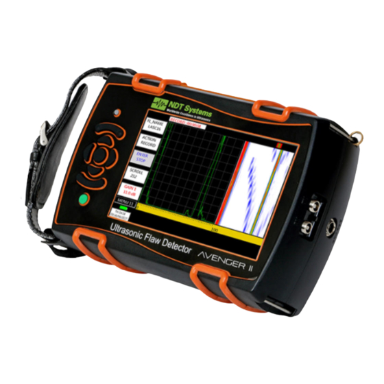
AVENGER II User Manual 3. Device Reference NDT Systems, Inc. P a g e 5542 Buckingham Drive Huntington Beach, CA 92649 PH: 714-893-2438... - Page 6 11. LCD SCREEN: Displays the A-Scan trace patterns, menu settings and other details. 12. USB DSK Indicator: This symbol is visible when a USB DRIVE is connected to AVENGER II or when the AVENGER II is connected to a PC.
- Page 7 29. PIN FOR HOLDING STRAP: Two Pins are provided for hand and neck straps. 30. STAND: Support Stand is provided for loading of AVENGER II on a surface. 31. CENTER KEY: Enter selected value, hold while incrementing a value to rapidly increment.
-
Page 8: Operational Menu Details
GAIN: Gain can be increased/decreased as per value of step by using GAIN UP/DN keys. Example: AVENGER II is to be calibrated for 100 mm Test Range using a Single Element probe. Using UP/DN keys navigate to RANGE in MENU 1. - Page 9 AVENGER II User Manual Menu 2 – MONITOR “GATE a” functions. GATEa GATE a : Gate can be changed to PLOGIC, NLOGIC, CRV M, CRV-1, CRV-2, CRV+1, CRV+2, EXPAND or OFF STARTa PLOGIC: When PLOGIC is selected, the MONITOR triggers if an echo is present 30.0 mm...
- Page 10 AVENGER II User Manual Menu 3 – MONITOR “GATE b” functions. GATEb GATEb : Gate can be changed to PLOGIC, NLOGIC or OFF PLOGIC: When PLOGIC is selected, the MONITOR triggers if an echo is STARTb present within the gate and its height is equal to or crosses the set 30.0 mm...
- Page 11 AVENGER II User Manual Menu 4 – Memory storage/recall and Trace printout functions. MEMORY MEMORY : Select A SCAN or SET-UP memory functions. A SCAN MEM NO : Select desired memory location from MEM NO. If Data is stored and MEM NO* valid, an asterisk (“*”) will be displayed next to “MEM NO”.
- Page 12 AVENGER II User Manual Menu 5 – DGS, DAC curve, and AWS measurement mode functions. Navigate to Menu 11 to select measurement mode DAC: DAC setting can be switched to DRAW, ON, OFF, TCG ON or TCG EDIT using STRT a LEFT/RIGHT keys.
- Page 13 AVENGER II User Manual DAC REF Gain In the DAC Draw process when user registers first echo signal, the equipment will automatically bring the registered echo signal to 80% height and Gain (Gain required to bring registered echo to 80%) is stored as REF Gain.
- Page 14 AVENGER II User Manual AWS: AWS setting can be switched to SET, MEASURE or OFF using LEFT/RIGHT keys. SET mode: Set GATE 1 to PLOGIC then bring reference echo of reflector in between 40 to 60% , Turn SET REF to ON key so gain of reference echo is recorded and START a displayed as REF GAIN.
- Page 15 AVENGER II User Manual DGS: DGS setting can be switched to SELECT, REF REC,ON or OFF using LEFT/RIGHT keys. In SELECT mode probe type, reference diameter, reference type, required DGS curve diameter, etc. can be selected. In ON mode DGS curve will be displayed on Screen as per what is selected in DGS selection menu.
- Page 16 AVENGER II User Manual SCAL NO : Scrolls from 0 to 18. Select “0” for a custom probe which is not listed. For custom probe select appropriate probe frequency and probe effective dia. PROBE : Displays model name of predefined probe.
- Page 17 AVENGER II User Manual Menu 6 – Damping, Crystal Type, PRF DAMPING DAMPING: Probe Damping HIGH/LOW can be selected using LEFT/RIGHT keys in DAMPING. MODE: Test Mode for the use of SINGLE or DUAL Crystal probes can be selected using LEFT/RIGHT keys in MODE.
- Page 18 AVENGER II User Manual Menu 7 – Thickness/Distance measurement functions. REJECT REJECT: Rejection level can be set as per requirement. Set in terms of percentage of FSH. Activation of this function is indicated by R Symbol (14). SMOOTH SMOOTH : Smoothness of the echo can be set to LOW, MEDIUM, HIGH OR OFF using LEFT/RIGHT keys.
- Page 19 AVENGER II User Manual Menu 8 - Thickness/Distance measurement functions continued. UNIT: Unit of measurement, mm or inch. UNIT COLOR: LCD Color combination can be selected using LEFT/RIGHT keys in COLOR. BRIGHT: Brightness of LCD can be adjusted for better visibility using LEFT/RIGHT COLOR keys in BRIGHT.
- Page 20 AVENGER II User Manual Menu 9 – Shearwave Analysis Functions. X-OFF X-OFF: Set X-OFF value to the front face distance for a correct surface distance 0.00mm reading. ANGLE ANGLE: Corresponds to the angle of wedge being used. When measure is set to ON, 0.0 DEG...
- Page 21 AVENGER II User Manual Menu 10 – HORN, Key Beep, Clock Settings. HORN HORN: The horn can be switched ON or OFF using LEFT/RIGHT keys. When HORN is switched ON, an audible alarm will sound when a gate is triggered.
- Page 22 AVENGER II User Manual Menu 11 – Evaluation modes for inspection, measurement settings from respective EVALMOD gates EVALMOD: Selectable evaluation modes DAC, AWS or DGS. As per selection of evaluation mode settings in Menu 5, will turn to DAC, AWS or DGS.
- Page 23 AVENGER II User Manual Menu 12 – UT DATA recording and evaluation feature. FL_NAME FL_NAME: Filename of the Recorded UT Data which is stored in the SD CARD. If Data LAS0001 is stored and valid then asterisk (“*”) will be displayed next to FL_NAME.
- Page 24 AVENGER II User Manual Menu 13 – ENCODER Inputs and Outputs. ENCODER ENCODER: When Encoder is set to ON, Encoder value will be displayed. CAL FAC: Calibration Factor value is needed to calibrate the encoder. CAL FAC Encoder Calibration: 1000 •...
- Page 25 AVENGER II User Manual Menu 14 – 2-POINT CALIBRATION. A CAL Zero and velocity values can be automatically adjusted using the two-point ECHO 1 calibration feature. This is useful for measuring materials with unknown ultrasound START a velocity. 30.0mm DIST 1 A CAL: AUTO CAL menu 25.0mm...
-
Page 26: Data Transfer
• Saved memory in SD CARD or USB DSK can be transfer to a PC. To copy all memories from AVENGER II to USB DSK or SD CARD switch to MENU 4, In MEM • NO select the destination SD CARD or USB DSK •... - Page 27 Time/Date set-up: Hold the UP key and switch ON AVENGER II. After the time and date menu appears on the screen, release the UP key. Set current time and date by using the LEFT/RIGHT keys. Press MENU DEC key to store the current time and date.
-
Page 28: Power Supply
AVENGER II User Manual 7. Power Supply The AVENGER II is powered by a Lithium-Ion battery pack (MB-1), secured in place by two screws and connected to the AVENGER II via a one terminal contact point. Fully charged, the AVENGER II can operate continuously for over eight hours. -
Page 29: Specifications
Calibration Set-up 50 different calibration set-ups can be Stored and Recalled. Software Interface software for transferring A-Scan from AVENGER II to PC is supplied. Display 5 Inch color wide VGA LCD/TFT display (800*480 pixels, size 108*64mm) with higher resolution LCD for better signal representation and better visibility with different color sets. - Page 30 AVENGER II User Manual Echo Dynamics Echo dynamic pattern display. Dynamic DAC curve can be digitally plotted (Smooth bolic curve) on screen with selectable offset curves from 0dB to 14dB in 0.5 dB selectable steps. DAC curve can be set as flaw monitor gate. Using minimum 2 to maximum 10 points.
-
Page 31: Warranty
AVENGER II User Manual 9. Warranty NDT Systems, Inc. Standard Terms & Conditions including its Warranty Terms can be found at https://www.ndtsystems.com/standard-terms-conditions APPENDIX I 30 | NDT Systems, Inc. P a g e 5542 Buckingham Drive Huntington Beach, CA 92649...
Need help?
Do you have a question about the Avenger II and is the answer not in the manual?
Questions and answers